I have had a 4kWp solar system for 10 years and not really thought about using the electricity I’m generating, for myself, until now! My layout is not simple, at the time I thought I was being clever by keeping the meter and panels etc away from the house, but now that I want to use my own generation for water heating, a car charger and a battery I have found that the meter and inverter and panels are too far away from the house for data communication between the two. None of the local solar installers can do anything with my system, because of the distance between the inverter etc and the house.
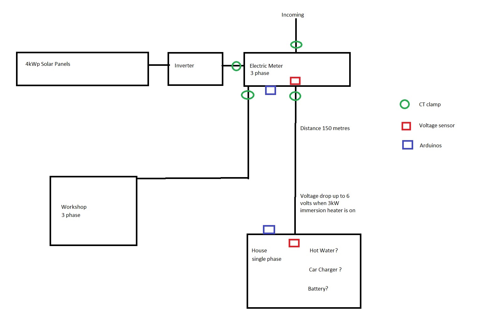
The house is nearly 150 metres from the meter and inverter etc, with an underground armoured single phase cable running to it. The voltage drop is up to 6 volts when the 3kW immersion heater is turned on.
The solution I have been considering is to have 2 arduinos talking to each other, either wirelessly or by using the underground cable with a powerline adapter.
The arduino (blue square) at the meter would need to have 4 CTs (green rings, for generation, incoming, shed and house) and a voltage sensor (red square), so that it can send available export data to the arduino in the house, which can be responsible for turning things on via one of the products designed for the job.
I have read up quite extensively the info on this site, and have constructed the circuit described here for the shed arduino. I found that the LMV321 opp amp is unavailable, so I used a LM358, is that an acceptable substitute? I used a protoboard, and the voltage section just seemed to be picking up every bit of interference going, which makes any power calculation meaningless. Should it be on as small as possible circuit board?
The appearance of “Car charger ?” at the house is worrying. A 2.5% voltage drop (= 6 V in 240 V) is the limit to comply with BS7671, so if you draw any more than 3 kW on a regular basis, you can expect appliances to not operate properly, and you might need to uprate the 150 m of cable, which could get very expensive. According to my tables, that cable must be 16 mm² anyway (2.8 mV/A/m). As you’ve got 3-phase at the incomer, if you find you have to uprate the cable, take all 3 phases to the house. Three-phase is likely to become more common for domestic supplies in the future.
Given high gain directional antennas, wireless (ISM band) is probably achievable provided you have a clear line of sight with no significant obstructions (like wet foliage), vehicles in the way.
I’ve no experience with Powerline, but I’ve read that distances of greater than yours are achievable.
I think my preference, if it’s practical, would be to install a ‘proper’ data cable. Ethernet over that distance might work but is outside the specification, though I did find this https://www.patton.com/poe-boosters/cl2110/ claiming to “double” that limit. Much more likely to be reliable is RS485 provided you use the correct drivers/receivers at each end.
The other concern I have is “Arduinos”. This is only anecdotal, but in the days when this was more of a constructor’s forum, most of the complaints about noise and pickup resulting in non-zero readings when there was no power flowing came from Arduinos with the analogue front end constructed on prototype board.
For that, almost any op-amp with a modicum of output current will do. Its purpose is to supply a voltage source (low impedance by definition) for the bias. You must make sure it doesn’t oscillate though.
That’s horribly familiar. Yes you should keep it small, you also need to observe all the rules for low-level analogue circuits, like watching where your grounding points are, make sure your supply is clean (and the ADC reference voltage, of course), and beware the noise that the digital part of your Arduino injects onto the supply. Make sure you don’t have loops picking up magnetic fields and aerials picking up electric fields.