Phase Shift query for unusual application

Hi!
I’ve installed an EmonPi with a CT sensor to measure the current on one phase of a water pump (slightly unusual use I know, but was just trying it out).

As the voltage of the pump is about 415V, I can’t install the AC power adaptor. I know that the Emon software assumes 230V for the voltage, if no sensor is applied, but what is the default phase shift? (I assume zero if it is mostly for home use?). I’ve been scaling the calculated power for a 0.8 phase shift for a water pump, and a higher voltage, and 3 phases.

I also have a hypothetical question as I’ve realised it isn’t possible because the pump is run off a VFD which doesn’t have a neutral output (it only gives 3 output voltages which are at 415V so too high). But if by sake of argument, it did have a neutral, and I could therefore wire up a plug going from neutral to phase, which would be at 220V (instead of the 415 voltage line to line), then could I use the AC transformer plug to measure the phase shift accurately?

When we calculate power, it is the line voltageline currentsqrt(3)*power factor.
Assuming I can measure line current, and infer line-line voltage from my measurement of neutral to line, would the measurement of neutral to phase and the measurement of line current give the correct power factor in the software to calculate power? Is the line voltage phase shift the same as the ‘neutral to line’ phase shift?

Not sure if that makes sense or if I’m being confused about nothing, but would appreciate someone who knows this stuff to help clear it up in my head!

Thank you!
Is this following on from Measuring AC current output from a VFD?

What sort of motor does the pump have, is it an induction motor, is it 3-phase or single? What voltage and power rating?

My first comment (after the above) is I think you’re getting a bit confused between power factor and phase. It’s true that in some circumstances p.f. = cos(φ) ; but those circumstances generally only exist in labs and text books. In the real world, it can be a decent approximation if you know when it’s safe to use it.

There are two ways out of that:

  1. You can use a 415 V : 9 V transformer instead of our a.c. adapter (AKA a 240 V : 9 V transformer in a case with a plug), or
  2. Make yourself a star point and connect the a.c. adapter to this. I’d use 3 identical high power resistors (250 W electric heaters - if your VFD can supply that, otherwise size to suit the drive).

If there’s no a.c. input detected, it only measures current, multiplies it by a fixed constant of 230 and calls the result watts. But it isn’t, it isn’t even VA, but an estimated apparent power using the assumed voltage. So it’s really amps times 230.

You definitely mean power factor there.

Have you checked with the manuals/the manufacturer? It’s possible that there’s a neutral, just not readily available.
Or have you measured the output voltages to earth?
What is the input to the VFD - 3-phase or single? If it’s single, measure the output voltages to the input neutral. If they’re all 240 V, there’s a good chance you can use that - at least for measurements with the a.c. adapter.

The way the emonTx software works is it takes alternate samples of voltage and current. Then it processes the numbers in 3 ways:

  1. It squares the voltage, averages it, takes the square root to give the rms voltage,
  2. It does the same with the current,
  3. If multiplies each pair of voltage and current samples together to give the instantaneous power, then averages those to give the average real power.

From those you get Vrms & Irms, multiply those two together and get apparent power, then it uses the definition of power factor = real power ÷ apparent power to give the power factor. Angles don’t come into it. (And so it can’t tell you whether the p.f. is leading or lagging from that.)

So yes, if you measure the line current and line-neutral voltage, the software will give you the power factor directly.

Thanks yet again for your speedy response and assistance!

Yes, perhaps I should have kept it in the same thread. I thought this was a slightly different question as it related directly to the fully packaged Emon-Pi.

I believe it is a 3 phase induction motor operating around 415V. The RSI/VFD supplying it is rated at 37kW though I don’t think its full capacity is ever used. I realise this is information that should be included on our wiring diagrams (which seem to stop at the RSI) so I’m finding out from those who know now.

Interesting news to me! I guess I’d only ever been taught textbook circumstances at Uni :frowning:

I think if I do it, I’ll opt for the safer option of buying a 415V:9V transformer (it did occur to me when writing the above, but I wondered if there was a cheaper option using the same supplied transformer). What is the reasoning for choosing 250W electric heaters? Would that not result in large amounts of wasted energy. Could higher resistance resistors not be used instead? It does seem as though induction motors have fairly predictable power factors though, so perhaps this exercise isn’t necessary if we are only after an estimation of power being used.

I’m fairly sure we’re using the VFD/RSI with just DC +/- input from solar panels, and 3 phase output. I can’t see from the datasheet any sign of a neutral, only an earth connection. Its the 37kW Grundfos RSI if you’re interested

It’s likely to be significant if your wave isn’t a pure sinusoid, which is almost a certainty if it’s coming from d.c. and your VFD. Sidetracking briefly into the details - what is φ: do you count it between zero crossings? I’d suggest the only valid value would come from doing a Fourier analysis on both current and voltage, which would give the amplitude and phase of each harmonic, and then calculating the power in the fundamental and each harmonic component. The definition of power factor is the ratio real power ÷ apparent power, which is easily calculated in the digital world.

I’d forgotten you were running off PV. The resistors need to be low enough so that the presence of the transformer (in parallel with one of them) doesn’t materially move the star point.

But first, I’d continue looking for something that can substitute for the neutral. Have you checked the output voltages to earth? If they are all the same and a sensible value (line-line voltage ÷ √3, then it’s worth connecting the a.c. adapter line-earth and check again. The drive may well see it as an earth fault and object, but if it doesn’t and the voltages remain balanced, then you can probably get away with leaving it there. The transformer primary current is minuscule compared to the 72 A that the drive is capable of.

That’s something for you to judge - I don’t know the ins and outs of what you’re doing, you do.

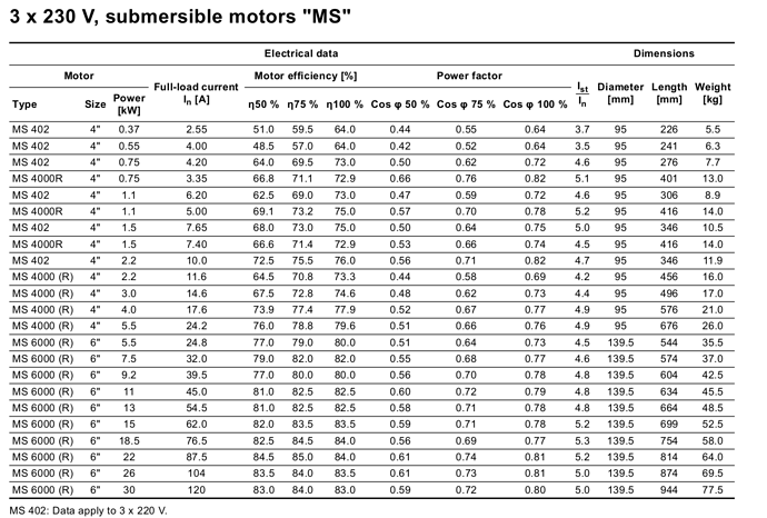
In my experience just the opposite. I’ve got a 1.5hp single speed, single phase synchronous pool pump and its power factor is very sensitive to mechanical load. When the pump is nicely loaded and everything is running as planned, it sits at about 0.98. When the pump is very lightly loaded (like sucking air) it drops down to about 0.5.

Your datasheet pretty much says the same for your pump:

You might even be able to use the measured power factor to tune your VFD to ensure the pump is operating at optimal loading.

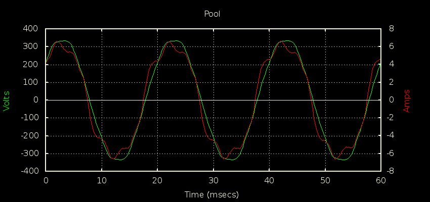
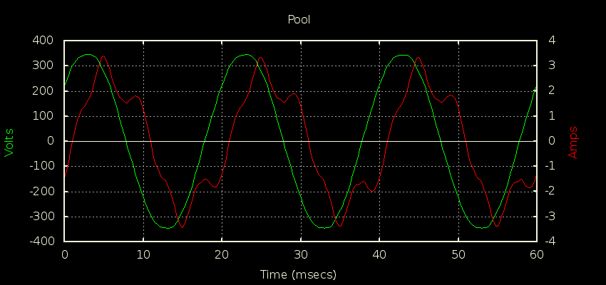
Here are two plots of my pump’s Current signal under various load conditions:


Normal ops, PF around 0.98


Pump very lightly loaded, PF closer to about 0.5 (from memory)

Great idea. I’ll try this the next time I’m on site.

Interesting, I am very clearly wrong in my assumptions. Not sure where I got the idea that motors were predictably around 0.8 when operating. Thank you for the graphs too! Definitely cleared that up.

I also just realised I accidentally linked the wrong datasheet above. This is the datasheet for the RSI. The other link was to some pumps I was just looking at (though I should have picked up on the power factors when looking!).

What do you mean by this? Do you mean that from the power factor, I could determine what loading/efficiency the motor is operating at, and then adjust the power being delivered to the pump to try and bring it back to a more efficient operating point? Sounds like an excellent idea, though I’m not sure our VFD can be programmed like that… My understanding is that the RSI has an MPPT to get the maximum power out of the panels, and then a VFD to enable the motor to run at that maximum power (which will likely be less than what the motor is rated for).

Yep, that. They even mention that in the original datasheet:

The operation of this water pump with variable duty
points may be more efficient and economic when
controlled, for example, by the use of a
variable-speed drive that matches the pump duty to
the system.

If there are no batteries involved, and the panels are dedicated to running just this pump, then efficiency probably doesn’t matter much (apart from initial sizing considerations). Once installed and running, you might as well throw all the power you can at it, since it’s free.