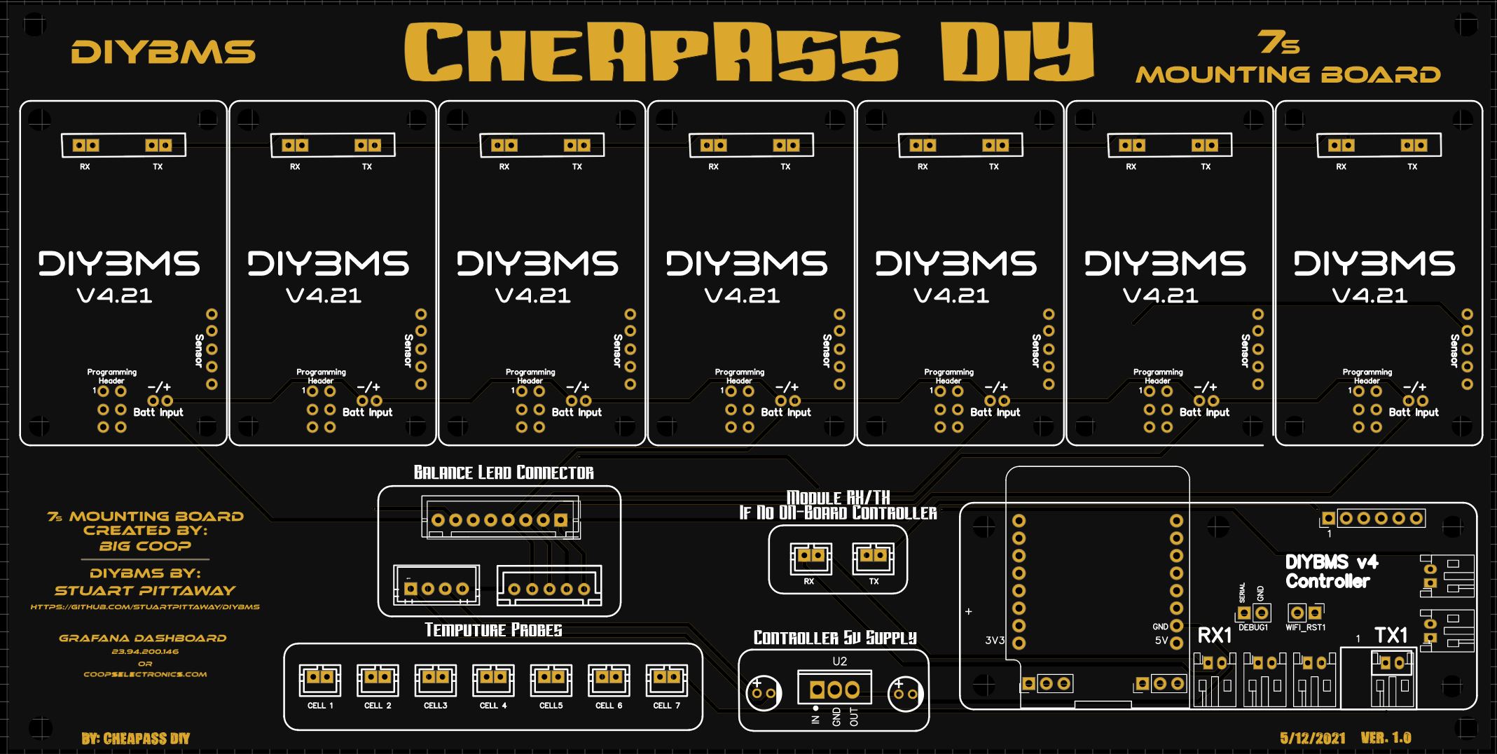
Just got done designing a PCB to hold 7 DIYBMS cell models and 1 Controller Unit. It also has a 5v regulator on-board to power the controller.
It’ll make a very clean setup. I just placed an order at JLCPCB and will let you know if everything works as planned next week.
I posted some pictures below. If anybody is interested, I’m going to make the EASYEDA project public. And if you would just like the files to make your own and not sure how to edit the PCB, just let me know and I’ll be happy to remove my “Nick Name” LOL or any small changes you may want.
Hey Jon, I’m curious about your use case here … based on the choice of 7s I assume your battery building block is lithium-ion chemistry for a 24V battery?
Was there any thought of making it 8-module/controller or 4-module/controller? With a hardware jumper on the board it would be simple to ‘jump around’ the 8th module allowing for 7 or fewer modules (couldn’t really tell if that was built in already).
Reason I ask is because I’m using lifepo4 and currently working on a 48V setup (16 cells … for a golf cart) … but I’m thinking I’ll reset and instead go to 2x24V … so 8 cells / battery since that’s my ultimate use case for RV house batteries down the road. The golf cart is my first foray into building batteries of any size (4.9KW) so my learning playground.
4 module version - 12V … the idea of a 4 module version would enable a very nice package for a portable lifepo 12V battery … I’ve made several of these as jump starters / aux camping power using headway batteries for myself and several friends. I end up charging them for everyone manually and have been thinking of putting a DIYBMS on them all so I can ‘enable’ my friends.
4 module version - in the spirit of scope creep …
There’s also the thought that a 4 module version could be used like building blocks as follows in a > 4 module string deployment…
Based on what I think I understand, a 4 module board could be connected to the next 4 module board that was, or was not, populated with a working controller. This would require that the controller on all 4 module boards have h/w jumpers onboard to connect/disconnect it’s controller tx/rx from the modules.
This allows for a built in spare controller already installed and ready to go that’s just not yet looped into the comms for the string. Or in your case, with 2 4-module boards strung together, a spare module and a spare controller.
For any battery deployment there would be a single active / connected controller … but it could be on any of the boards in the system and deployments could be any size given current capabilities.
Another thing I really like about the approach is that regardless of the modules / board it will be a simple matter to put the BMS into an enclosure with provisions for cooling that’s appropriate for any situation be it battery bay in a RV/vehicle, golf cart or static deployment. Dealing with the wiring and module placement on the golf cart has proven to be a real headache for me so far with the constraints I have (it’s unwieldy … and ugly!!).
Thoughts?
Stuart, am I off the path here with the building block idea … seems too easy but your design would seem to support it (to me at least).
See any show stoppers? Would there be concern with the potential for creating more noise on the comms with the un-terminated tx/rx jumpers? Seems like this could potentially make it better.
Yeah that’s totally do-able. I had almost designed the original PCB to hold only 4 cell modules and one controller, that way the boards could be purchased from JLBPCB for only $0.50 or less since they would be within 100mm x 100mm. And either add a series of dip switches or Jumpers to link multiple boards together if it was for bigger than a 4S battery. And obviously only use one controller.
Give me a few days, and I will Design up a PCB that can hold 4 cell modules with the ability of linking multiple boards together.
I’ll probably design it, so could string 3 of them together for 12s battery. Since 12s is pretty common. I can’t see making it infinitely expandable, since I have to include a balance lead connector. Since the whole idea of this PCB is to keep the wiring down to a minimum and make everything neat and tidy.
And I’m open for suggestions you or anyone else has any ideas of things to implement etc…
I’m really interesting in this project of you Jon.
I want to use a 14S battery pack so can I use two of those boards and connect them together somehow ?