Hello guys,
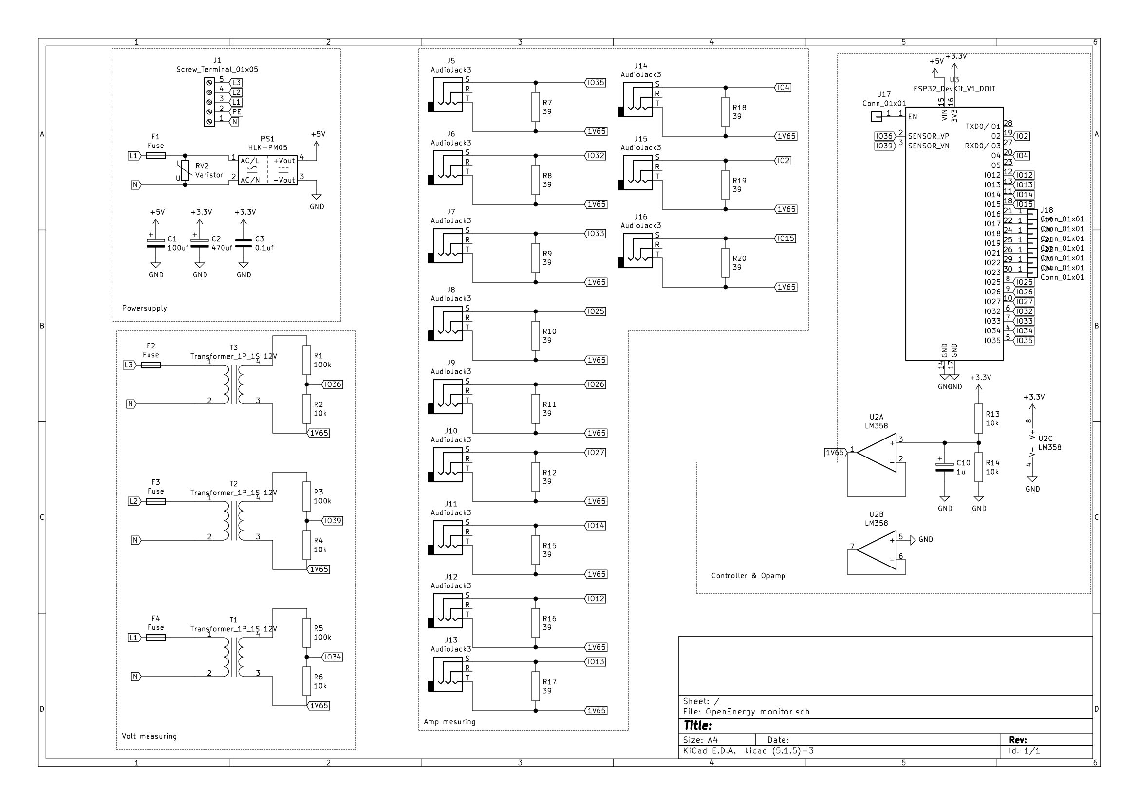
As a project I’m designing a PCB that I can put into my fuse box to measure the power usage and generation, we have solar panels, of every group of my house. We have 3 phase power so that’s why it haves 3 transformers to measure the voltage of every face separately.
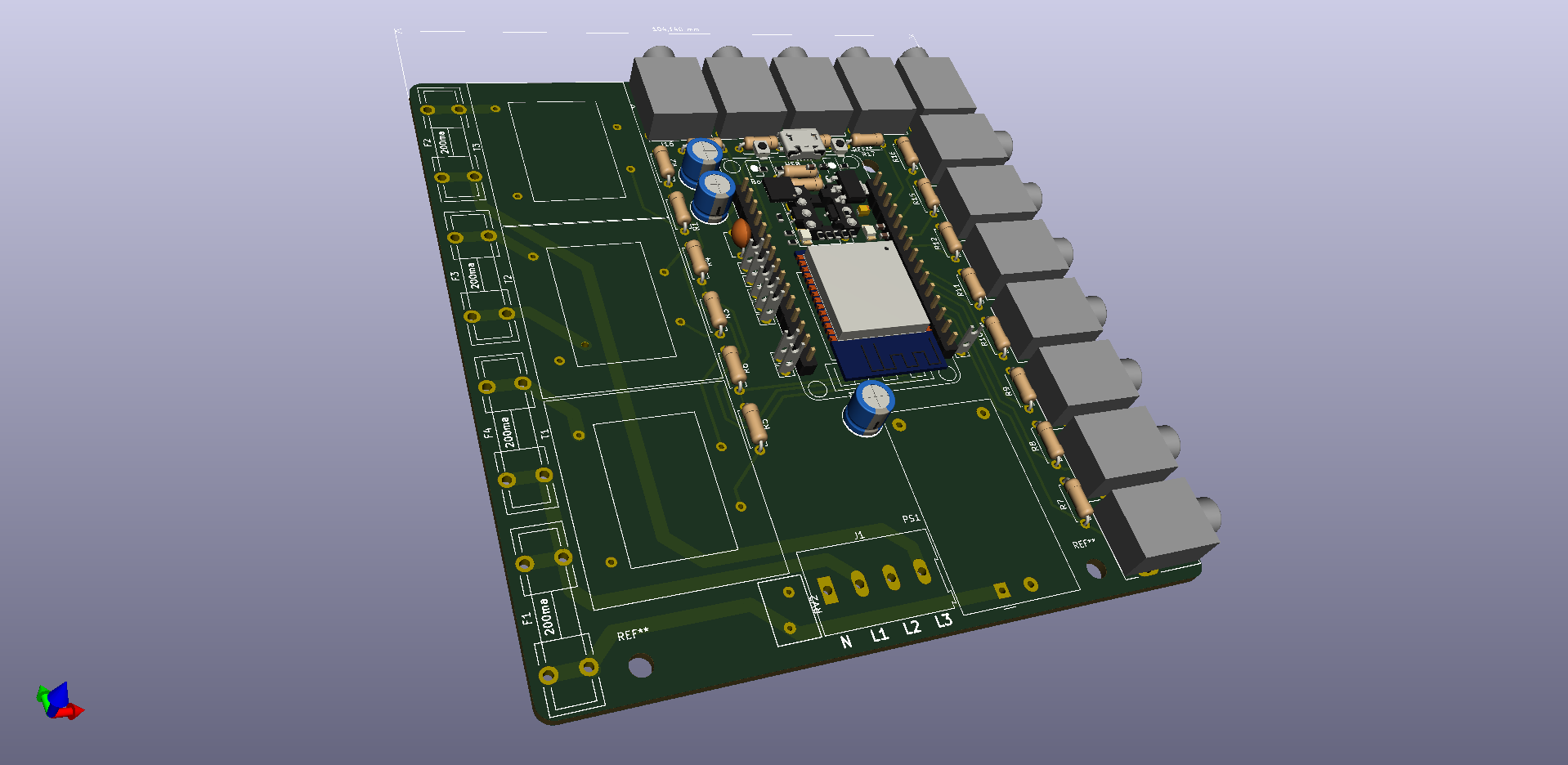
As a controller I wanted to use a 30pin EPS32.
Before I continue to order the PCB’s and parts I thought that there will be some people here who are a lot smarter and more experienced than me.
Can someone give me some advice about my design in term if operation and manly safety.
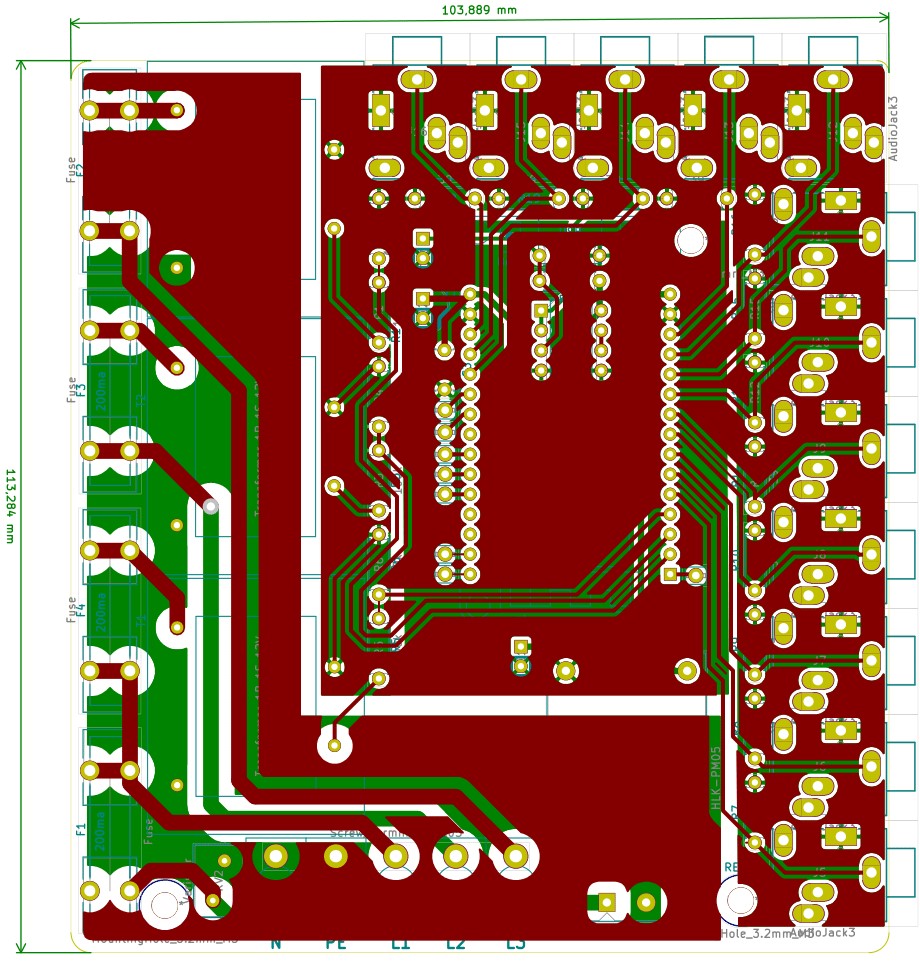
Without dimensions, it’s difficult to judge, but those tracks with 415 V rms (≈625 V peak at maximum voltage) look a bit close.
I’d be tempted to put an earth on both sides between those and the low voltage side, so that any creepage would be to earth, hopefully blowing a fuse or tripping your RCD.
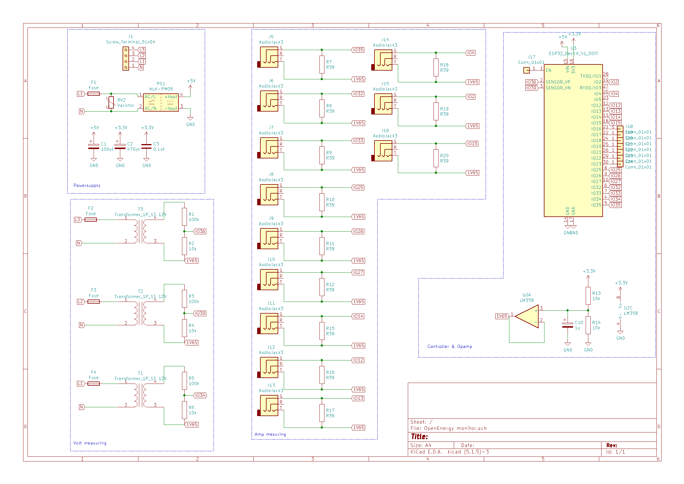
Will your 1.65 V bias be stable, given the amount of capacitance on it? And remember to not leave the second op.amp in that package floating.
Have you checked the no-load voltage of the 3 transformers? With 12 V secondary windings, the no-load voltage could be about 17 V, in which case your 100 kΩ / 10 kΩ divider is wrong. The input to the ADC at about 4.3 V p-p will be good for a 5 V input, not a 3.3 V one.
What current transformer are you using? - 0.39 Ω with a 3.3 V input swing raises my suspicions - it implies a 2.8 A rms secondary current, which is almost certainly outside the rating for a 3.5 mm plug and you track width, and equally almost certainly wrong.
And why have you connected the tip of the jack to the reference bias rather than the sleeve? We do it that way in the emonTx so that we can use the ‘break’ contacts in the socket to short the input to GND to detect the presence of a c.t. or not. You cannot do that with your op.amp driving a common bias, so there’s no need to make the plug sleeve the input signal - unless it’s so that you have a convenient test point .
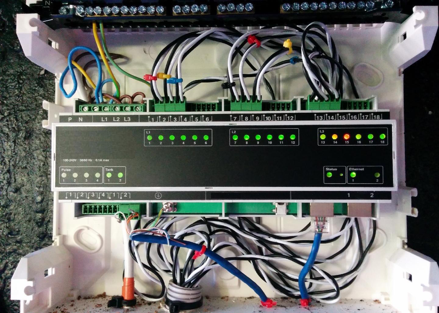
I’d second @Robert.Wall’s comments re track spacing, but also include the connectors. You need a 7.5mm spacing between the L inputs. Something like the top left connector here:
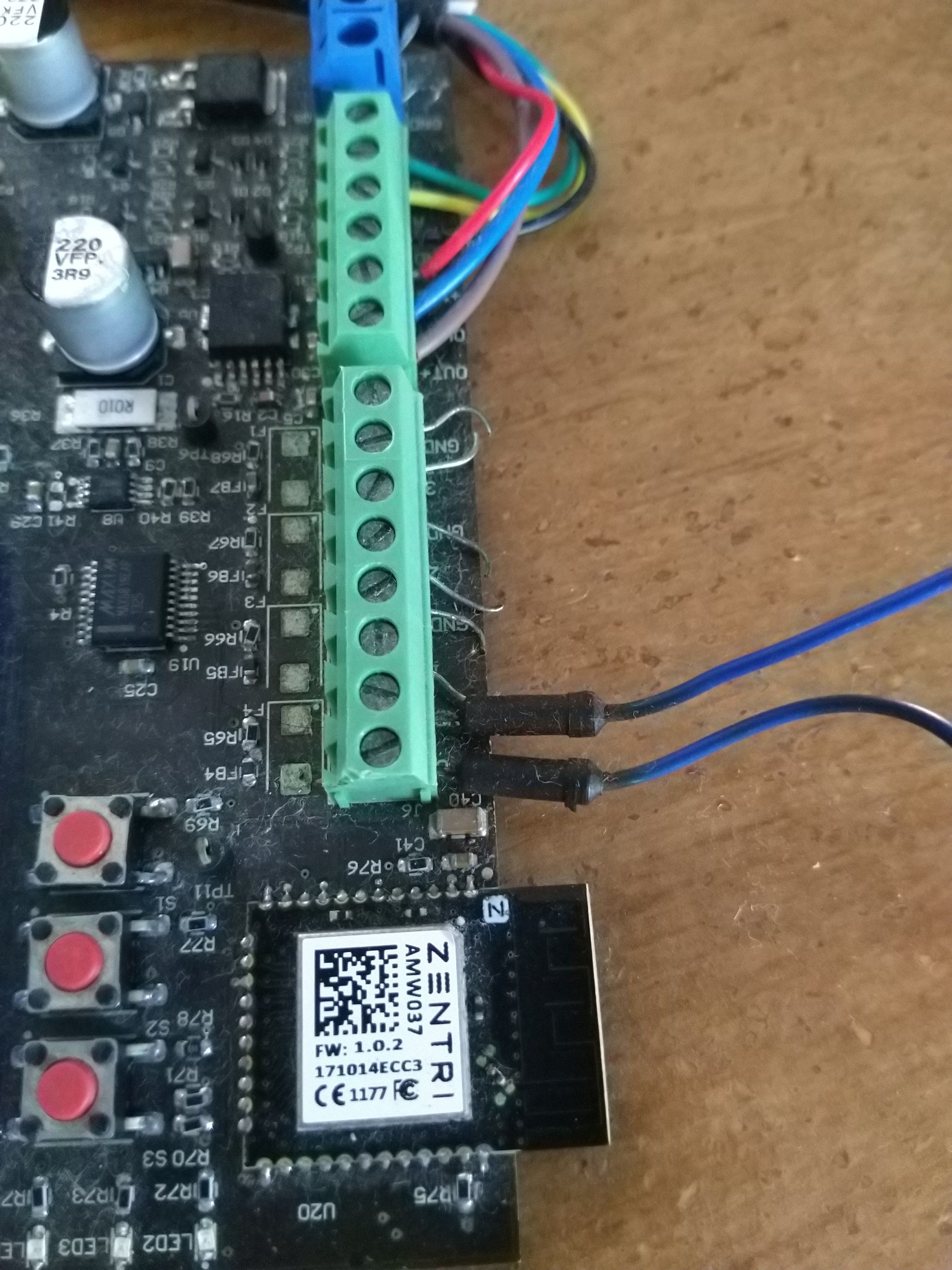
I clipped one of the connectors of the transformers for testing and measured where the lead ons the plugs are going to. This shouldn’t be right? I will check.
I will use a PCB antenna bud it is a EPS32 Devkit board so it is 1cm elevated from the main PCB. I’m gone take my changes with this one, else I have to re do everything bud I will take this into account the next time. Also, our wifi router is in the distribution box so it probably will be fine.
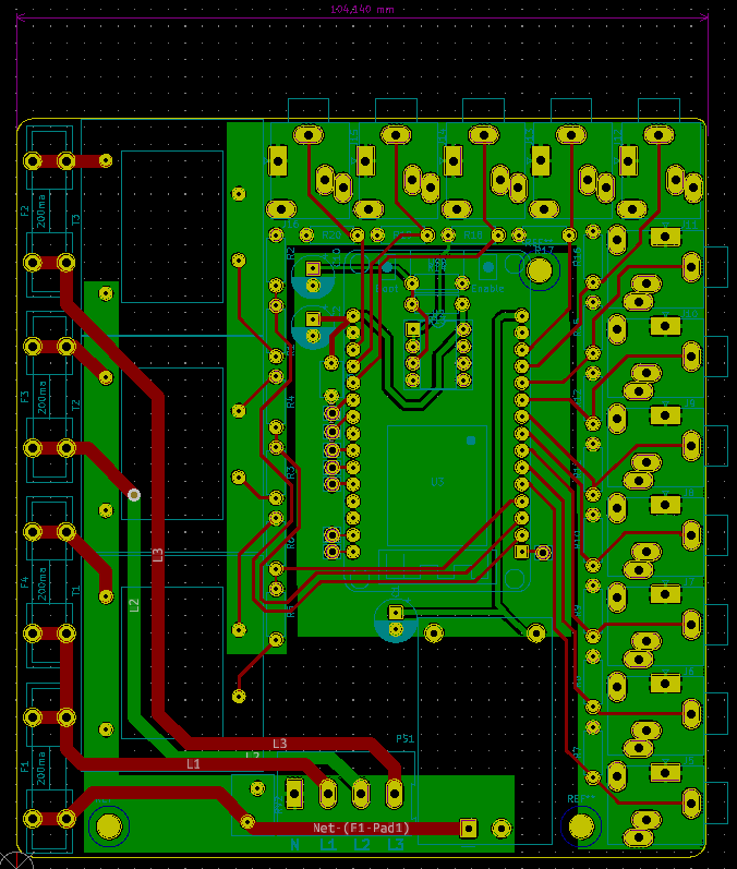
I changed the power connector to one with 7.5mm like you advised. I also checked the trace spacing. This is everywhere minimal 2mm now. This is enough if I’m not mistaking.
You did not need to cut the plug off - that is our “standard” c.t. and we know what the connections are. Tip and sleeve are correct, there is no connection to the plug ring, and normally the cable screen is not connected at either end. My comment was that I think it would be better, on your p.c.b., to connect the plug sleeve to the 1.65 V bias supply, as that is more likely to accidentally contact something else. But it’s not an important point.
As you are using those c.t’s on individual circuits at low currents, they will not be very accurate - accuracy is only guaranteed above 10 A. IF you are able and it is legal for you to disconnect a wire to fit them, you might like to consider the Talema www.talema.com “AZ” series. They are available from RS Components https://nl.rs-online.com Talema AZ- series and there are three versions, 25 A, 40 A & 50 A, all of which have a 50 mA secondary current so compatible with the SCT-013-000 and your 39 Ω burdens. Those will be more accurate at low currents, and are physically much smaller, therefore it will be easier to fit many inside your switchboard. But you will probably need to extend the wires and fit a plug, or use screw terminals instead.
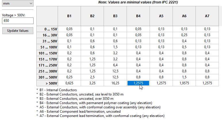
If you use a safety standard like IEC60950, you’ll end up with 5mm. Here’s a calculator based on 60950. It’s that 5mm spacing requirement that forces you to the 7.5mm connectors.
I would go for 8mm between primary and secondary. Actually, I think you had that in your original design but lost it when you put that ground plane in.
Not really related to your board layout review request, but have you done your own tests on the ESP32 ADC? I’ve not used one, but it seems to get a pretty bad rap. I don’t know whether that’s down to people not using them correctly or them being deficient. It would be a shame to put all that effort in only to discover the ADC wasn’t up to the task.
Treating the secondary side as an unearthed SELV circuit (because there’s no guarantee that it is earthed, and even if it is, you don’t want leakage currents reaching the ADC inputs or the ADC reference voltage), the IEC60950 calculator shows a creepage distance of 13.4 mm is necessary. The ground plane (screen) intercepts and grounds leakage currents, so it becomes an earthed SELV circuit which requires Basic insulation and 6.7 mm creepage distance.
Ah OK, I forgot about the safety earth connection. So long as Sander didn’t. @SanderV, you plan running a real safety earth yellow/green wire to this thing, right?
I did a little proof of concept test with a ESP 8266 bud I will discover how precise the ADC in this thing is. Channel 2 of the ADC is also used by the Wi-Fi so I have to disable Wi-Fi before I read the ADC. I also just read that ADC is not really linear as this chart shows:
But I read somewhere that there are library’s with lookup tables for this. Perhaps I have to consider using a separate ADC with i2c and a smaller controller, esp8266 or something.
We have a smart meter with a RPI connected that keeps track of the total power usage in the house. So I could accurately check the accuracy of the hole system this way.
This hole project started with measuring if the washing machine was ready but I figured that if I did that why not take it a bit farther. It would also be nice to keep track of the power generation of our solar panels because our power meter only measures returned power and not the total generated power.
That is not good for what should be a straight line. If that graph is accurate (it is yours, or the one you have is the same as that), I think you might be better to use a range from 0.15 V to 2.6 V, giving a peak - peak range of 2.45 V centred on 1.375 V (say design for 0.78 V rms to give some allowance for component tolerances, etc). You must design the analogue part to take account of that.
I think I would prefer to do that rather than use a lookup table, because while lookup tables are fast, they will still slow the sample rate, which is quite important when measuring distorted waves.
I don’t have an ESP32, so I can’t measure the sample rate you might get. My guide is you must sample faster than the 13th harmonic, and the absolute minimum for that is 2 samples per cycle. And you need to sample current and voltage and switch between them. Multiplying the numbers:
50 Hz × 13 × 2 × 2 = 2600 samples/s, and that is without pausing to do any calculations based on the numbers.
EmonLibCM does exactly that with the AVR processor, because the ADC can run independently of the main processor, generating an interrupt to allow the processor to handle the maths while the ADC measures the next sample.
Using analogRead( ), the ATMega 328P that we use can read approximately 55 pairs of voltage and current samples per 50 Hz mains cycle. Running the ADC continuously, it can read one sample every 104 µs, or ~96 pairs of voltage and current readings per mains cycle.
(13th harmonic is an arbitrary choice, there should be very little power above that frequency, if all the appliances you have are well-designed. There could however be a larger proportion of power above that frequency from low-power devices like lamps that are not as strictly regulated as the high-power appliances.)
Hmmm, I never really thought aboud that. As far as I know the ESP’s are more power full then a Arduino so I never saw it as a problem. Bud I don’t know how this is managed when the wifi turns on to send the data ETC.
I do have a ESP32 here so I could do some test next week. I’m not specially skilled or something in the abilities of the ESP bud I will do my best.
Bud it sounds more and more like it would be better to offload the measuring to a separated controller or ADC.
 .
.