We are investigating EmonEVSE hardware upgrades to negate the need for an earth rod, however I cannot give you a time frame on this.
If an earth rod installation is not possible, a Matt-E device to provide an earth disconnect under fault condition:
We are investigating EmonEVSE hardware upgrades to negate the need for an earth rod, however I cannot give you a time frame on this.
If an earth rod installation is not possible, a Matt-E device to provide an earth disconnect under fault condition:
Hi, is it correct to say that to comply with new regs (18th ed. amendment 1) openEVSE outside should be installed with:
Should internal GFI be removed?
Hi @roberts
Short answer yes but not just outside. All EVSE now need to have open PEN protection whether inside or out.
The Matt: e or similar just removes the need for TT earth (rods).
You will always need the functionality of type B rcd (for DC fault protection). Some EVSE has this built in. As of last year OpenEVSE didn’t (but I’m not up to date with that)
I believe you don’t need to remove the internal GFI/RCD - why would you want to?
Discrimination?
FWIW the Matt:e variant with type B rcd is the SP-EVCP-B
@roberts
I will follow this thread with interest given I’m in the market for a 3 phase EV charger
Thx
Thanks for the comment @EskEnergy - it’s nice to talk about those things with other people who are interested in electric vehicles!
I was asking about removal of GFI because I remember seeing somewhere a note to not to disconnect it. I was wondering if it plays a part in functionality of the equpment - e.g. check to allow charging to start.
Regarding other comments, there are few common misconceptions for domestic installatons I think I should address.
Those devices are not a requirement in BS 7671:2018 (+A1 2020) at all. In fact 722.411.4.1. says that PME supply should not be usd for EVSE outdoors unless one of five conditions is met, where this Open PEN detection device is just one of the options.
If the vehcle is charged outdoors there are other options, for example, installing additional earth electrodes, converting existing installation to TT, TT system for EVSE only or isolation transformer.
Open PEN detecion device is never needed if the EV is charged inside and there is no posibility to use it while EV is outside. CoP 6.7.1. repeats that PME can be used within a building without rods (or open PEN devices for that matter), but gives aditional suggestion that non-extended tethered lead only should be used (key - you should not be able to be in contact with true earth and PME earthing).
722.531.3 specifies what type of RCD is needed for EVSE. That is:
*Type B RCD or
*Type A or Type F in conjunction with RDC-DD.
From my experience if Type B RCD is not installed, Type A RCD is used together with a residual direct current detecton device (RDC-DD) that can detect if the DC component exceeding 6mA and disconnect the supply. Those devices might be built-in in EVSE or can be installed seperatly.
In 18th edition it is called Co-ordination or selectivity. Yes, if you install RCD in your EVSE distribution board you might have issues with coordinaton with RCD/GFI. CoP recognizes that sometimes it might not be practicable to folow it. This is the reason why I was asking if GFI is required for functionality of the OpenEVSE.
Roberts
I consider my wrist suitably slapped!
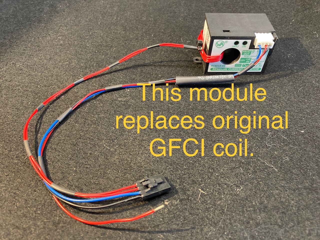
I have managed to integrate the Western Automation RCM14-03 module into the OpenEVSE unit.
This gives AC 30mA and 6mA DC GFCI protection (tested and confirmed). While there are several methods of integrating the module…I wanted to simplify the integration so that DIY builders can easily upgrade their units without having to make modifications to the actual controller board or firmware.
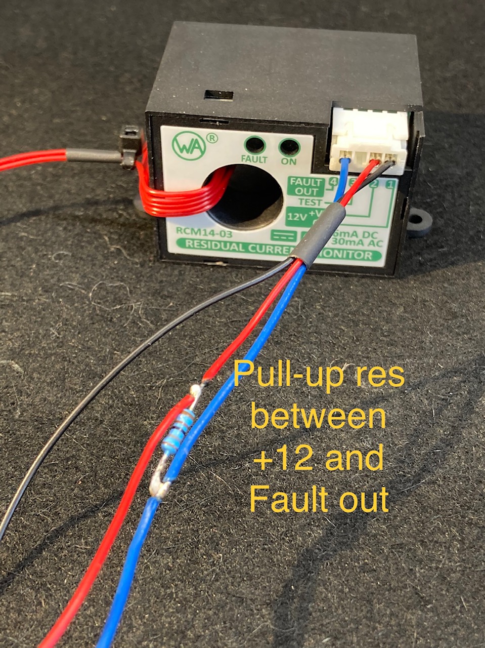
The RCM14-03 gives a ‘HIGH’ output on its [FAULT] pin via a pull-up resistor when leakage is detected.
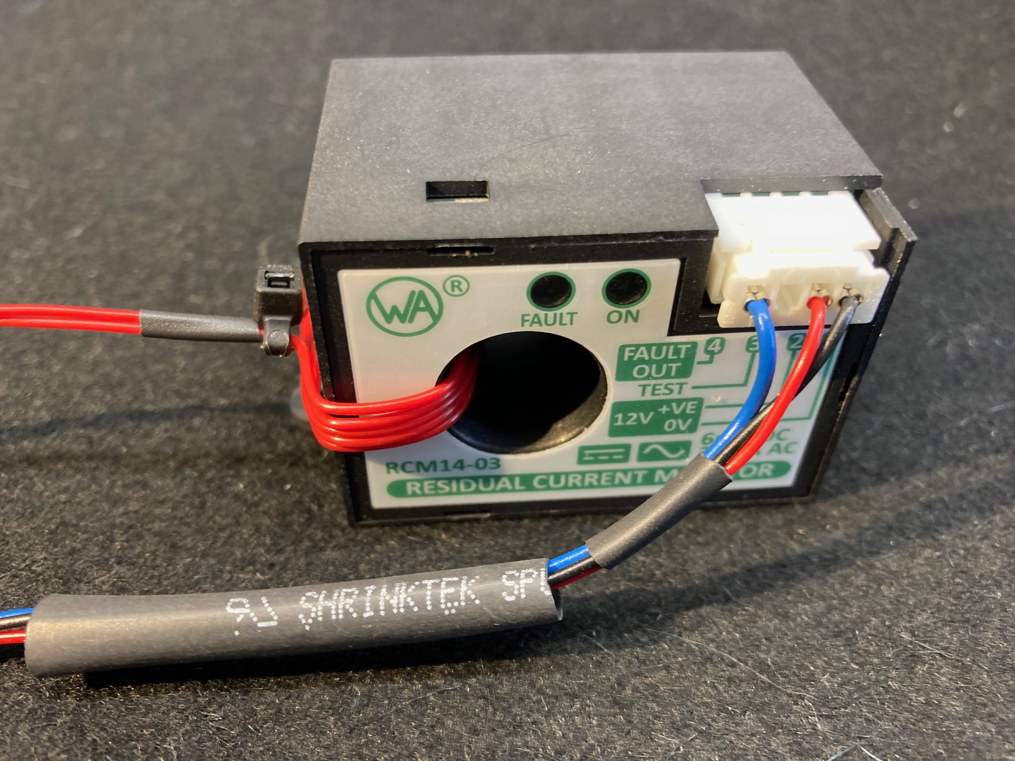
This [HIGH] signal can be directly coupled to the sensor input (pin 2) on the GFCI connector. The value of the pull-up resistor is selected (1k2) to level shift from 12V operating level to the 5V input of the GFCI detector.
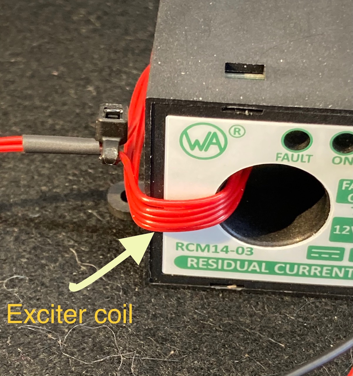
I added an ‘exciter’ coil to the RCM14-03 so that the self tests will run without issue. I also made a custom cable with integrated pull-up resistor so that the module can be fitted easily to the controller board.
I received great support from the R&D department of Western Automation who are the manufacturers of the necessary modules.
Please see pictures attached.
Just been reading this brilliant thread and would like to add that in the COP for EV 5.2.3 unless it can be guaranteed that the supply is TNS back to source, ie your own transformer. TNS should be treated as TN-C-S.
Very good.
Thank you for sharing!
Nice work! That’s very tidy integration. Have you been able to find a source to buy the RCM14-03? Will westernautomation sell direct? I can’t see any pricing info on their website.
Nice work on the DC earth fault workaround. Did anyone find a good supplier (cheap) for the RCM14-03 in Europe at reasonable pricing? Are there any other supplier in the market for similar than Stegen?
We notice that Go-e Charger is using the Bender RCMB121, could not find pricing anywhere on their coil. Has anyone looked how difficult the integration to OpenEVSE would be?
It would be great if this could be made to work with the openevse system, though squeezing this is the case would be fun 
John
Great integration Cyril! RCM14 module needs 12v to operate and my question is did you take 12v from OpenEVSE controller board? I have OpenEVSE v 5.5 but unfortunately the 12v output is used for WIFI module.
Andrej
Yes Andrej. I paralleled the 12 volt supply. It’s difficult to get both wires into the tiny terminals.
Cyril
Thanks Cyril for the good news. Just one last question is it enough power supply for both WIFI and RCM14 modules to work properly?
Andrej
Yes. It’s been working perfectly for me for the last 6 months.
Cyril
I received the RCM14 unit from Stegen Electronics and I am finishing integration with OpenEVSE module. I would like to check the resistance for the pull-up resistor which should be put between 0v and Fault connector. As you wrote the resistance should be 1.2 k Ohm but if I look at the photo and put the colours of the resistor (brown, brown, black?, silver?,silver?) in calculator, I am not able to get 1.2k Ohm. Of course it could be tricky to get the right colours of the resistor from photo…
Andrej
It looks to me as if the colours could be brown-red-black-brown-brown, which would be a 5-band code 120×10¹, making it 1200 Ω, 1%.
Ah. I see that the colours are not represented properly in the photo. It’s brown red brown. Definitely 1.2k
Cyril
I’ve dropped the image into Gimp, saturated the colours and enlarged the resistor.
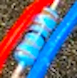
I think the bands start nearest to the camera, because there appears to be a bigger gap between the band furthest from the camera and the next. If it is an E12 series component, the possible values - given the first band is brown - are 10, 12, 15, 18. If it is an E24 series, the values are 10, 11, 12, 13, 15, 16, 18.
I think the first, 4th & 5th bands are the same colour, brown.
The second band is definitely not black (0), green (5), nor blue (6). I think it might be grey (8), orange (3), or red (2). As we are told the value is 1.2 kΩ, then I think that is correct.
@Gwil - I tried to upload that image as .webp - it won’t accept that now, has Discourse updated itself?