i will install this in my house and would be good to use the SO counter instead of the led sensor, but trying to avoid opening emonpi. Any ideas?
Thanks
Celso
You can use the pulse input on the RJ45 connector. Using a device with an SO output has been mentioned a few times - I’m not sure about this forum but certainly in the ‘Archived’ section, and the emonPi input is exactly the same as on the emonTx (so if you find something about the emonTx, it also applies to the emonPi).
Thanks for the advice! When i was searching, was only here. I never remember the archived forum.
Just one thing, will emonpi need the 10k resistor?
Ondrej write that since raspberry pi already have one, i assume that emonpi too.
Thanks for the help!
That is correct, but for the wrong reason! The emonPi uses the internal pull-up resistor in the Atmel 328P (the pulse input does not go into the Raspberry Pi), therefore you need to connect your SO output between Pin 6 (IRQ1 - SO+) and Pin 5 (GND - SO-)
Thanks. I am afraid to burn my emonpi so the reason that i am making so many questions. I am going to try and then i will sugest add the procedure to the wiki.
Thanks Robert.Wall!
The only way you might damage your emonPi will be to connect Vcc and GND together - possibly via your SO device. Don’t do that!
The only thing wrong with the Wiki is that it does not mention the internal pull-up resistor, but that is not part of the hardware, it is inside the processor and it is enabled by a line in the sketch.
Yeah, thats the main reason that i have been searching around and making so many questions. Since i dont know much about electronics, a small action could mean a big problem, so i need to be sure of what i am doing.
The electrician will install the meter in my eletrical board saturday and i will try it then next week. I will post the results then.
Thanks for help!
By the way, is emonTH able to connect to open collector? It is powered with an atmega328 and have the same GND and IRQ1. But i couldn’t find about the resistor.
If i install emoncms to a simple raspberry pi and connect the SO open collector, wich pins should i connect?
(Raspberry pi model B)
My brother has a raspberry pi and since i don’t know much of it, i am afraid to mess it up.
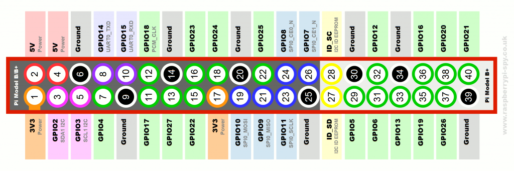
Paul’s script there appears to be using pins 13 & 15.
If the software is applying a pull-down, you connect the SO output between the GPIO pin and the 3.3 V power.
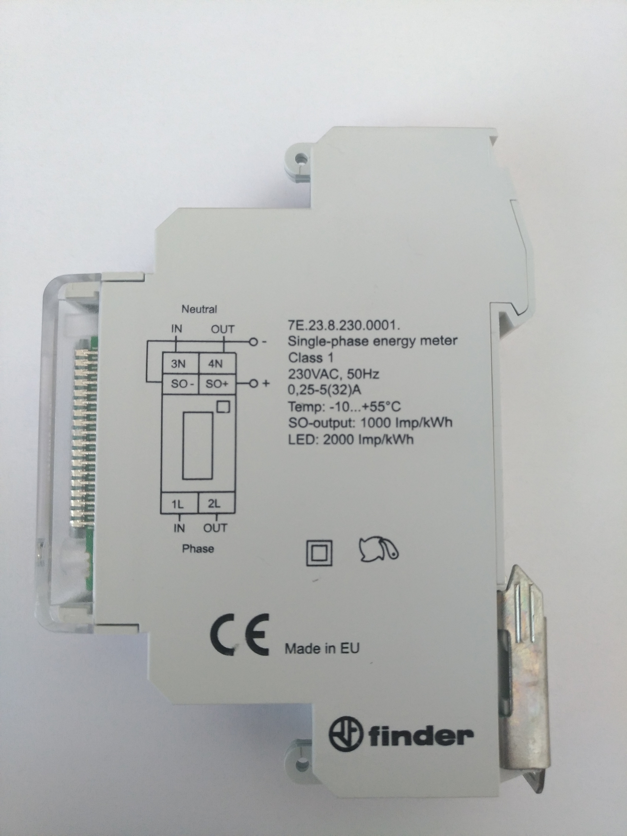
S0- output on energy meter to GND on RaspberryPi
S0+ output on energy meter to GPIO[x] on RaspberryPi
No external pullup resistor for the S0+ line is required as the RPi internal pullup will be enabled by the software."
So, its confusing me at connecting the wires, as it don’t talk about the 3.3v.
And searching on the web, as i dont have much knowledge of electronics, i couldn’t find any “simple” explanation for my lack of knowledge.
And shouldn’t emoncms detect the input, once its connected?
I think the explanation is simple. One chose one way, the other person chose the other way. Both are valid ways of getting almost the same result.
Paul Burnell has chosen to connect between +3.3 V and GPIO pin 13 (for his 1st input) and has specified “pull down” in software pull_up_down=GPIO.PUD_DOWN; and the GitHub contributor has chosen to connect betwween the GPIO pin and GND, and has chose “pull up” in software.
The choice is yours. The difference is what the ‘contact closed’ means in software. In Paul’s case, it is a logic 1 (true), in the Github case it is a logic 0 (false).
Now that you explain that, i can see how it works.
How did i miss this(???):
“So if you wire the switch between input and ground, so the switch pulls the input to 0 V when it’s closed, you need a “pull-up” resistor to pull the input up to 3.3 V or 5 V when the switch is open. And vice versa”
Well, the open collector will be the one that i posted at the beginning.
The choice will depend of what emoncms allows me to do without messing up much with the system files but i would like to avoid burning anything so, connecting it to gnd is the most safe decision.
Actually, i thought that was just connect the wires to the open collector and emomcms (i installed the latest image provided by openenergymonitor on a sd card) would detect it automaticaly (sorry, not sure if is well translated).
Already have a emonpi connected to the collector, i assumed that was just connect the raspberry pi with the same software and the result would be the same. Didn’t know about the logic and the pins.
It will take some time to learn and see, as i dont want to bothering everyone every 5 min and i want to learn how to do it.
If you want to use the pulses.py script with pull-ups and wire the switch between ground and input, you just edit the 2 pull_up_down=GPIO.PUD_DOWN lines to pull_up_down=GPIO.PUD_UP.
The pull-up or pull-down is just to counter the way you wire the switch, the sketch will work the same way, the pulse is just the change of state and the pull-up or pull-down is to ensure the state does change and not hang/float.
Think of the pull-up or pull-down as a spring, if your switch or sensor is “pushing” the switched wire down to ground you want it to spring back to 3.3v when it’s finished ie pull-up (to 3v) If your switch is pushing the switched wire up to 3.3v, you want the “spring” to pull it back down to ground when it’s done ie “pull-down”.