Hello,
I finally end the “hardware and soldiering” part of my system.
Is based on a Arduino mkr1000 + 1 SCT013-030 (30A/1V) + 1 SCT013-020 (20A/1V) + Voltage transformer 230V/9V Ac-Ac
High freq noises coming from sct sensors are filtered with a Sallen-Key Low-pass Filter system based on 1 Op Amp lm358 dual with one side CT30A and on the other side the CT20A.
Filtering noise I have less than 0.1A residual when CT are with “zero primary current state”. I’m happy about these first step resault…
Now I’m trying to calibrate the system with some real load. I chose a bath heater 3 power levels. on the box was write pow1 800W pow2 1200W pow3 2000W.
I have a Digital multimeter HT4014 with a good resolution to see real data VS Energymonitor data.
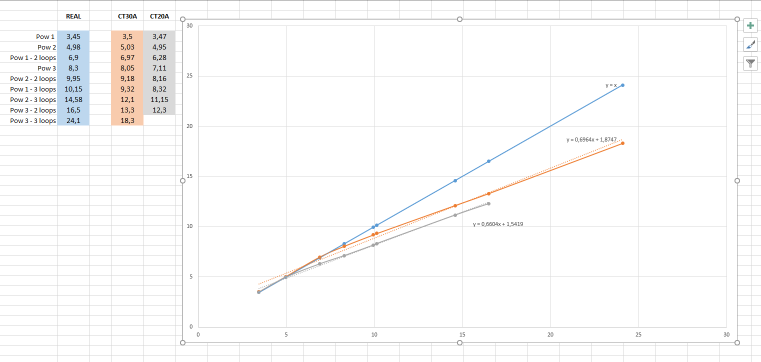
I’m surprise about resoults:
on one hand Voltage transformer is very very precise. I have error < 0.5%
on the other hand CT are not precise after a fraction of the total range.
with low primary current , readings are very precise
after 6/7 A (about 20%/25% the range of 30A CT) errors start to grow
at 20 A error is 2.5A/3A.
Can some one help me to understand why with “mid-hi” rmsI values error is big? I suppsed to find some kind of linearity on CT output
How can I do in order to improve my precision?
If you look at the FAQ page, at the very beginning is
“Please don’t link to files on external sites. Unlike others, we want you to attach your screenshots, log files, etc to your post. If the external site goes away, the material is likely to be lost forever. If that happens, when someone reads your post, your question and our answer will have little or no value.”
I think you should look at the data sheet for your LM358.
On page 1, under “Features”:
■ Large output voltage swing 0 V to (VCC+ -1.5 V)
That means the output can only move between 0 V and 1.8 V. Now, if your input is biased to 1.65 V, it can swing by only 150 mV in the positive direction. That is less than 10% of what you need.
I think it is likely that the positive half of the current wave is being clipped and that is reducing the rms value that you calculate. That is why the graphs fall away.
You can easily test to see if this theory is correct by temporarily removing the filter, or better, if you can borrow an oscilloscope, look at the shape of the wave.
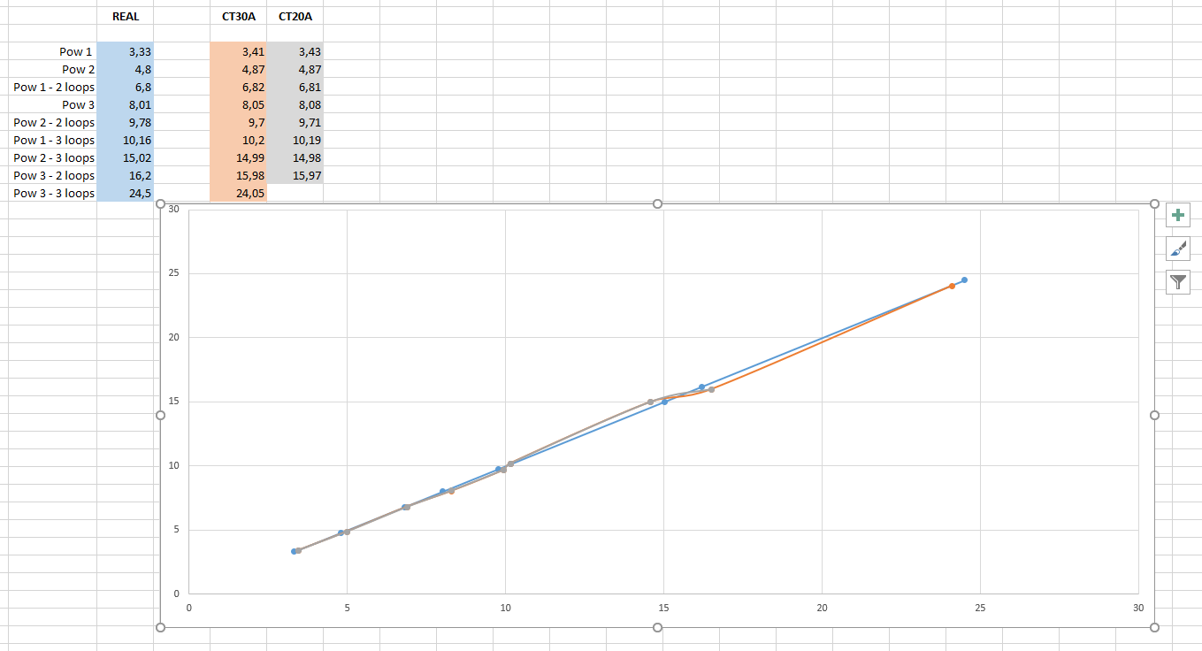
A possible solution would be to add a second burden to your c.t’s so that the output voltage is limited to 150 mV peak at the maximum current you want to measure, then make up the loss by altering the calibration in software.
You could improve on that by reducing the bias voltage to 0.9 V, then you would have a peak voltage out of the LM358 of 900 mV (1.8 V peak-peak), which would mean less reduction of the c.t’s output voltage would be needed.
According to my notes (from data supplied by Overeasy) the internal burdens are 93 Ω for the 20 A (not verified) and 62 Ω for the 30 A (verified by @gby). With those values, you can calculate the value of the required parallel resistor and the correction to your calibration.
OMG. Thank you. I looks many time on lm358 datasheet but I’m didn’t realize that!!!
As you can see i’m not really expert in electonics stuff, i’m learning, and this kind of stuff if difficut to aim to the correct information on first experinces. Thank you, I’d never suspect it!!!
Do you also know the name of alternative and correct op amp I really hope to substitute the opamp only and not remake everything.
You need to use the website of a major distributor and look for an op.amp with a low supply voltage, single supply and “rail to rail” output. One that looks promising, but I have not studied the data sheet in detail, is the TLV2762. It is not cheap, however.
I hadn’t looked at that one, but at a quick glance, it looks OK. I’m sure there are many op.amps that will be suitable. And as the trend is to use lower and lower supply voltages, I can see the choice becoming even wider.
I think Nicola, your problem arose from selecting a general purpose ±15 V supply op.amp – with a 30 V swing potentially available, 1.5 V off the top end isn’t all that important in many cases. But running at 3.3 V, it makes a huge difference. As the available voltage gets lower and lower, it gets more and more necessary to use an op.amp that’s designed with that in mind.