Only emonPi2 CT inputs 1 and 4 work

This feels like a PEBKAC problem, but for the life of me I can’t figure it out:

I have a new emonPi2 (Pi4B) with a 3-phase EmonVS (currently only hooked up to one phase - US split phase power - on V1). The system as a whole is basically working: I can login; see the phase voltage; and see the power/energy from my first CT, a 50A one from the shop, on one leg of a 240V heat pump water heater. I have stumbled my way through doubling the voltage to approximate the full 240V and logging power / energy from that input. I’ve also hooked up the pulse output from a water meter to log water usage. So far, so good.

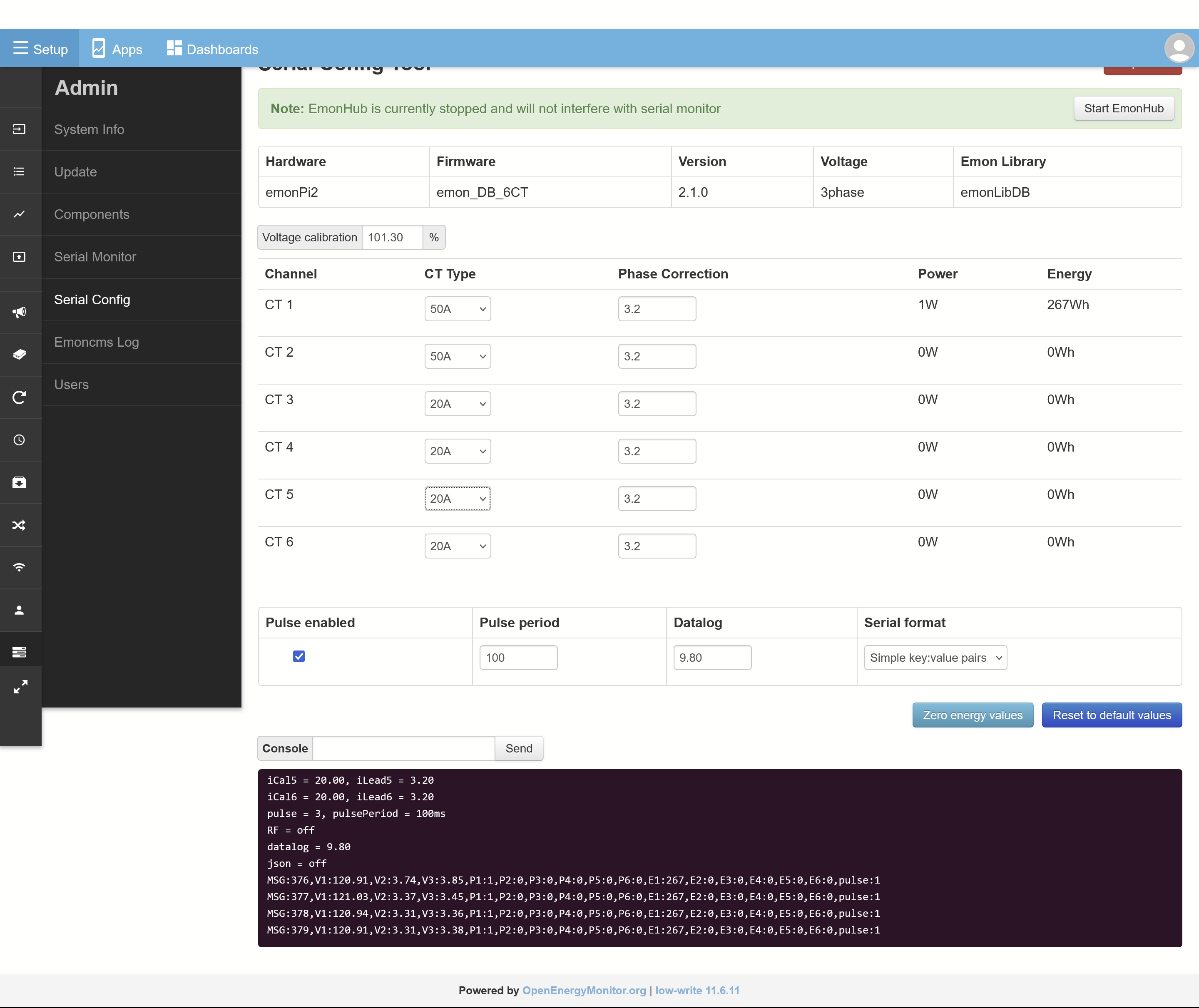
So now that I have a basic idea of how this all works, I’m hooking up two more CTs, both 20A parts from the shop. I’ve clipped them around my hot wires, and have confirmed they’re working (both by measuring V_AC coming out of them with a DMM, and by plugging them into the CT1 input on the emonPi2 and watching the input get reported (albeit incorrectly, as they’re 20A CTs plugged into an input configured for 50A) in the Inputs list). But when they’re plugged into inputs CT2, CT3, CT5, or CT6, nothing is reported. CT4 reads accurate values (matches my kill-a-watt plug meter), despite never previously having had anything plugged into it.

I’ve plugged the next two CTs I’m installing into CT5 and CT6 inputs and power cycled the emonPi2 because I read there’s some auto-detection that happens at power-on, but to no avail. I even plugged in all 6 CTs (two 50s into CT1 and CT2; four 20s into CT3-CT6), and gave them some dummy load (only about half an amp) and power cycled with that physical setup. Stubbornly, only CT1 and CT4 will return values. The other four inputs report 0 power. They can’t be misconfigured in terms of which voltage input to use, because V2 and V3 have some residual noise on them and report a couple volts: any reading whatsoever should result in some non-zero power value being reported in http://emonpi/input/view

Still, disabled inputs seems like the most likely source of my problems. How do I determine which inputs were auto-detected, and can I force them all to be active? Is there something else I should be doing to trouble-shoot?

Thanks in advance for any pointers y’all can give me!

Forgot to mention: emonpiRelease: emonSD-01Feb24

And I think I’ve figured out an answer to one part of my question: in the Serial Config Tool, the console reports iCalx values for the detected CTs:

service-runner trigger sent for '/var/www/emoncms/scripts/serialmonitor/start.sh 115200 /dev/ttyAMA0'
Loading configuration, list (l) command sent:

firmware = emon_DB_6CT
version = 2.1.0
hardware = emonPi2
voltage = 3phase
vCal = 101.30
iCal1 = 50.00, iLead1 = 3.20
iCal2 = 50.00, iLead2 = 3.20
iCal3 = 20.00, iLead3 = 3.20
iCal4 = 20.00, iLead4 = 3.20
iCal5 = 20.00, iLead5 = 3.20
iCal6 = 20.00, iLead6 = 3.20
pulse = 3, pulsePeriod = 100ms
RF = off
datalog = 9.80
json = off

…or just iCal1, iCal5, and iCal6 for when I only had those three after a power cycle. Interestingly, in that case, the P4 power input still worked when I hot-swapped the CT from input 6 to input 4. I don’t know if any of that is diagnostically helpful.

Welcome, Ben, to the OEM forum.

The emonPi2/emonTx4 3-phase configuration by default pairs the voltage and current inputs as:
CT1 - L1
CT2 - L2
CT3 - L3
CT4 - L1
CT5 - L2
CT6 - L3

So there’s your problem - no voltage on L2 & L3, power calculation comes to zero. (And if your emonVs were the single phase version, some components for L2 & L3 are omitted. :cry: )

I don’t have an emonPi2 (even though I wrote the library it uses!) so I don’t know how the serial config tool works and whether it allows you to change the pairing of current and voltage. If you can, that’s the easy way.
The second easy way is you have a 3-phase emonVs: link L1-L2-L3. It will work as 6 single phase single channel monitors, and give you the correct values for 120 V loads, but you’ll still need to double the power for 240 V loads.
The third, probably hard, way is to edit the sketch in the Emon part (not the Raspberry Pi part) of your emonPi to use the correct pairing of voltage and current. You can link any CT (current) to any voltage - the limitation is purely in the default software in the Emon part. I can give you the changes if this is what you want to do. (And you’re not the first in N.America to have this problem.)

Thanks so much!

I wondered if the 1-and-4 pairing was a clue:) But I talked myself out of it being due to phase voltage because L2 and L3 are both reporting about 3V. I guess there’s some input sanity checking where those are treated as exactly zero when computing power (rather than ~3V * ~500mA is ~1.5W)?

If I’m willing to edit things as you suggest, would that let me correctly monitor 240V split-phase circuits (CT1 and CT2 will both be large 240V loads, so they should use L1+L2 as their voltage) too? Or is that already built into the software, rather than being part of the CT<–>phase assignment you’re talking about, and I just need to RTFM some more? I hacked in the factor of 2 as a ‘good-enough’ option to move forward, but I do intend to eventually hook up both phases, which is why I picked the three phase emonVS.

I’m more of a hardware guy than a software guy; how much tinkering are we talking about here? ssh in and modify a config file sort of thing? I haven’t gotten that far yet, but the docs say a long press on the button will enable ssh (until next reboot?) so that should be readily doable.

P.S. Is the default binding between CT inputs and emonVS phases documented somewhere that I’ve missed (got a link?)? Probably there’s other useful information nearby that I should be reading too.

No, the question is: Where did the 3 V come from, and what does it look like - wave shape and phase? Because 3 V rms × 500 mA ≠ 1.5 W if the 3 V comes from random noise or the wave is somewhere close to 90° out of phase in relation to the current. The power is the average of the instantaneous samples of voltage and current multiplied together - so if you do the maths for the particular case where you have two pure sine waves 90° apart, the average over on cycle is exactly zero. If one is exactly n times the frequency of the other, the same applies. If one is pure random noise, then “big numbers” theory says the long-time average is again zero. There is a check for “acPresent” in the library - but Trystan decided for some reason not to use it in the sketch. So I think no real power detected is the more likely explanation - power rounded in the library and sent to emonCMS as an integer in watts. So < 1 W would report a zero.

Yes, the library is capable of this.

It’s a bit more involved that that. The way I’d advise (and bear in mind I’m a Chartered Electrical Engineer by profession - it’s just that as part, only part, of my job I’ve been writing software since the days of 110 baud teletypes :sob: ) is to download the Arduino IDE and the libraries you need and compile the front end sketch on your main computer, then transfer it to the Pi and thence to the Atmel-DB processor in the ‘Emon’ part. I know the Docs recommends something called platfromio, I can’t help you if you go that route, because I tried it and it screwed my machine up - once bitten, twice shy.
The instructions for setting up the IDE and libraries are here: Firmware — OpenEnergyMonitor 0.0.1 documentation

What you need to change in the file emon_DB_6CT.ino:
(Before you do, I suggest doing a test compile as it comes to prove everything works.)

Lines 289 - 294 are where you do the changes. In the emonLibDB documentation (which you downloaded), the API is explained in detail.

  EmonLibDB_set_pInput(1, 1); // Phase 1
  EmonLibDB_set_pInput(2, 2); // Phase 2
  EmonLibDB_set_pInput(3, 3); // Phase 3
  EmonLibDB_set_pInput(4, 1); // Phase 1
  EmonLibDB_set_pInput(5, 2); // Phase 2
  EmonLibDB_set_pInput(6, 3); // Phase 3

My guess for your changes based on what you’ve written will be:

  EmonLibDB_set_pInput(1, 1, 2); // Legs 1+2
  EmonLibDB_set_pInput(2, 1, 2); // Legs 1+2
  EmonLibDB_set_pInput(3, 1); // Leg 1
  EmonLibDB_set_pInput(4, 2); // Leg 2
  EmonLibDB_set_pInput(5, 1); // Leg 1
  EmonLibDB_set_pInput(6, 2); // Leg 2

We describe your supply as a single phase, split into two legs, because they come from a single centre-tapped winding on the transformer.

Note - it takes a bit longer to do the calculations using the two voltages, so the sample rate is necessarily reduced. This is automatic. You’ll still get 24 samples per channel per 60 Hz mains cycle based on all 12 CT channels in use.

Yes, here: Firmware — OpenEnergyMonitor 0.0.1 documentation

No, it’s short presses to cycle round the menu until it asks the question, and then it sticks until you do it again. :smiley:

Your problem - a big one - will be detecting what you don’t need to read immediately. There’s a huge amount of stuff here in Docs, so don’t try to take it all in unless you have a photographic memory.

Thanks again, Robert! That’ll keep me busy for a while.

It gave me the nudge I needed to go find the emonPi2 schematics, whereupon it became clear that ‘sketch’ means AVR code specifically, so I anticipated that part of your answer. Probably there’s a clear line in there as well for switching one of the external temp sensor inputs to pulse sensing, if I decide I want another water meter input. And then I’d have to figure out the corresponding emon changes so that’s a project for another day. I’m not sure what the “SL” refdes means (“shorting link” is my best guess), and I’m not familiar with the decal in the PCB either, but once I open the thing up it’ll be clear how to move that around.

I’d made the simplifying assumption that probably the V1 input was coupling into the adjacent V2 and V3; V2 does report slightly higher than V3. But you’re right that it could just be random noise, and it could be both together: it wouldn’t take much random noise to push the voltage measurement up to ~3V while the in-phase component coupled in from line 1 would result in <1W of measured real power. I hadn’t thought of that.

Time to go get familiar with the AVR toolchain…

Yes, sorry. It’s Aduino-speak for the application software.
(I’d probably use “schematic” and “layout” or collectively “drawings” for what you found. To me, ‘sketch’ when not in Arduino context means a rough hand-drawn diagram, illustration or plan.)

There’s only one pulse input set up, lines 327 & 328

  EmonLibDB_setPulseEnable(PULSE_PIN, EEProm.pulse_enable);
  EmonLibDB_setPulseMinPeriod(PULSE_PIN, EEProm.pulse_period, FALLING); // Trigger on the falling edge

Your lifeline is the emonLibDB documentation - just replicate those two lines for your second pulse input and tweak accordingly. If in doubt, look at the examples that came with the library - every API call is illustrated (though most do nothing extra/different because they set the default value!). Do read about PulseMinPeriod, because the ‘sketch’ default is often not appropriate.

Details of the solder links for pulse counting are here: Other sensors — OpenEnergyMonitor 0.0.1 documentation

There are worse. And some a lot better. Try Arduino 1.8.19 rather than 2.x.x. At least it allows your choice of editor, which 2.x doesn’t. (or which the Linux version 2.x doesn’t.)

It’s been a busy year so I’m just now getting a long weekend to play with this.

I followed the instructions at Firmware — OpenEnergyMonitor 0.0.1 documentation .

I got the IDE installed. I got libraries installed, and also the bits of OpenEmon firmware. A suggested, I did a test compile of emon_DB_6CT which seems to have gone well enough (one default argument warning in the RFM69_LPL-main library, but it compiled).

Then when I change the #define from EMONTX5 to EMONPI2 things start going downhill. First I run into the missing SSD1306Ascii library, which is easy enough to find, but then it complains that Wire1 is not declared in this scope, in emon_DB_6CT.ino:205:

//----------------------------------------Setup--------------------------------------------------
void setup()
{
// wdt_enable(WDTO_8S);

// Indicator LED
pinMode(LEDpin, OUTPUT);
digitalWrite(LEDpin, HIGH);

// Serial
Serial.begin(115200);
print_firmware_version();

// OLED display
// Very simple starting message and then
// control is passed to the Raspberry Pi
#ifdef EMONPI2
Serial.println(F(“Starting emonPi2 OLED”));
delay(1000);
Wire1.swap(2);
[...snip lines >205...]

I can comment out the four calls to Wire1.swap, Wire1.begin, Wire1.setClock, and Wire1.end and it’ll compile. Given the comments that suggest this is just giving a pre-RPI output to the OLED, that’s probably safe. It looks like the Wire1.* calls are setting up the bus so that the subsequent oled.* commands actually actually DO print “emonPi2\nstarting…” which reinforces the idea that it’s safe to ignore that section of the setup function: probably I only really NEED the two pinMode() calls.

But if this doesn’t compile for my hardware, then it can’t be the code my emonPi2 is running, which means I’m making unintended changes, and may be making more of them than I realize. And without a way - that I know of, anyway - to backup the current config to go back to factory settings if (when) I screw something up, I hesitate to plow forward in cheerful ignorance.

You’ve been quite generous with your time; could I trouble you for another pointer or two? Thanks, and happy Thanksgiving!

I can’t see where “Wire1” is instantiated. It might be a Spence-Konde special version of the One-wire library, or it might be the standard Arduino “Wire” library. I don’t know, I wrote emonLibDB and only the demo sketches to illustrate its use, Trystan did the application sketches for the emonTx4/5 and emonPi2.

The thanks noted with gratitude, but happy Thanksgiving means nothing to me, I’m genuine English.
:grinning_face_with_smiling_eyes:

I figured out - I’m fairly certain - the Wire1 issue. Once you’ve picked a board in the tools menu, there’s a “Wire (Wire.h/I2C) Library mode” setting that shows up. The screenshots in the docs (Firmware — OpenEnergyMonitor 0.0.1 documentation) show it set to 1x Wire, but when it’s set to “2x Wire, Master or Slave (>28 pin only)” then the compile errors go away. I haven’t traced the code through to see where exactly that happens, but it makes sense, and it works, so I’m calling that one solved.

Looks like I’m allowed to post images, so there should be a screenshot above.

While noodling around trying to figure that out, I stumbled across the pre-compiled binaries I’d somehow managed to miss the first few times around, which gave me confidence I could get back where I started even if my binaries wouldn’t work…but they seem to work fine, and I’ve incorporated Trystan’s recent commits too.

This time there’s no holiday - just a weekend with some free time - to blame for me working on this some more. So, absent a holiday, happy eve-of Tom Bawcock’s Eve, which Wikipedia tells me is a more regionally appropriate holiday for your side of the pond:)

I’ve successfully switched around the inputs and confirmed they’re doing what I expect; thanks again for your help!

1 Like

Now I’ve NEVER heard of that! But I have heard of Stargazy Pie.

Hmm… That compiles for me, and always has. Maybe something has been corrupted in your source or a library?

But surely, temperatures are handled directly by the RPi, so I can’t see why the Wire library is needed in the front end - or maybe I’ve lost track of where you’re at.

I still have more investigation to do. From a purely software perspective it sort of makes sense that you’d have Wire for a single I2C controller, and Wire1 for a second one. So when you configure the project for a second port you’d get Wire1 too (and the project compiles fine with ‘1x Wire’ if I change the Wire1. invocations to Wire. which further supports that idea).

But the schematics are clear that only one I2C interface is used; there are four sets of potential I2C pins in the AVR: two sets are no-connects, and the third is configured for CT1 and ANALOG_INPUT (to the analog expander header, which I can’t readily use since I have the PI2 model that doesn’t have room for it in the case). And the code’s clear that it intends for “Wire1” to refer to that one and only I2C interface: it’s the one connected to the OLED:) And also, after it’s used for that, it gets switched into a generic pin input mode:

pinMode(PIN_PB2, INPUT);
pinMode(PIN_PB3, INPUT);

with a comment saying it’s releasing the bus for the RPI to use it:

// Very simple starting message and then
// control is passed to the Raspberry Pi

and I can see that in the schematics too: the I2C bus that goes to the OLED is shared with the AVR and the RPI connector.

My working hypothesis was that this one I2C bus is the ‘second’ one - thus Wire1, and the apparent need to configure the project for 2x I2C controller mode - but you’re saying it works as-is for you (with #define EMONPI2, right?), so it’s not just an omission in the emon docs. And so apparently I have more work to do to understand what’s up.

It’s unclear if I’m actually getting the AVR-driven OLED output (I need to add a healthy delay in there so it’ll be visible if so) prior to the RPI taking control, but at least CT1-6 and the first two voltage inputs from the emonVS are all working, and I can change the channel / phase assignments and see my changes have their expected effects. I haven’t tested the pulse or analog inputs but I see no reason why they’d be affected by any I2C shenanigans.

I’m taking a proper couple weeks’ holiday shortly, so I’ll revisit this further in perhaps mid-January. Have a great rest of 2025!

1 Like