A client has a NIBE 2050 monoblock ASHP in a well insulated house in Suffolk.
Install was by a local firm under the umbrella of Nuheat; yes Nuheat who’s business model includes selling as many zone controllers as possible. They provide the design and certifiaction and the plumber installs it. Its a common set up if not ideal.
We just got the emonpi data flowing after 18months of tinkering from afar.
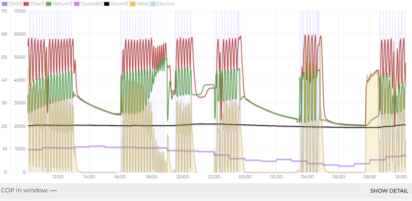
Its behaving very strangely.
Its cycling every 10 minutes. Flow temperature is far hotter than weather curve or hot water would require.
The emonpi is confused on what is heating demand or hot water.
I don’t think it is the nuheat controllers as the behavior happens even if we set them very high.
We checked sensor positions, seem OK, and is set deep in the sensor pocket.
Maybe the DHW sensor is wired to the wrong ports in the diverter valve. Or, maybe the diverter valve itself is wired wrong.
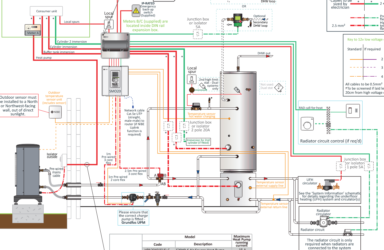
Do you have access to the myUplink data that the NIBE controller should be uploading to their servers (assuming that’s connected to the Internet)? The NuHeat schematic mentions a Cat 5e UTP cable and “NIBE Uplink” - which has been retired, replaced by myUplink (which does the same thing).
You really want to have visibility of:
Parameter S1, which is the Target Flow Temperature calculated by the NIBE controller, based on the WC Curve (potentially influenced by the target Room Temperature too)
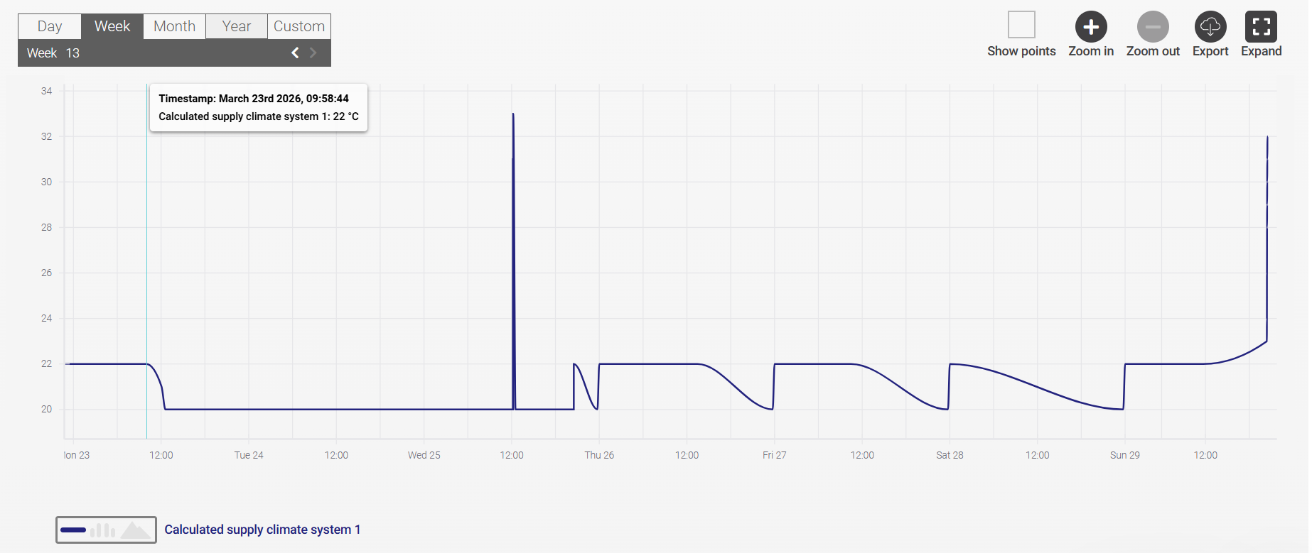
Parameter BT25, which is the Measured Flow (“External Supply Line”) Temperature
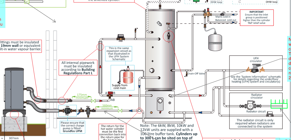
The sensor for that should be in a pocket on the buffer tank under the DHW cylinder
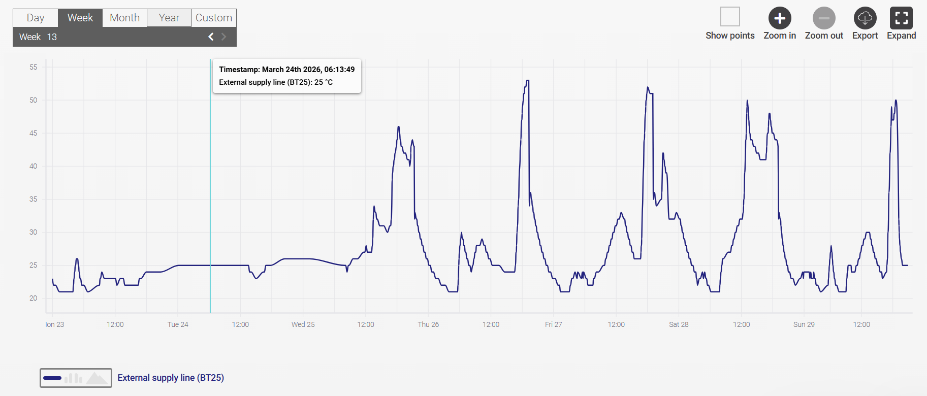
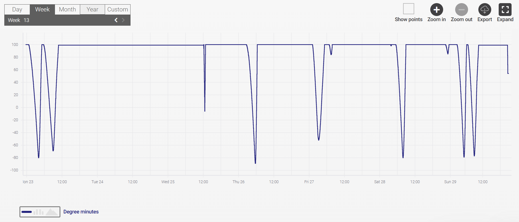
The “Degree Minutes” running total that indicates how well BT25 is tracking S1 and which is directly related to the algorithm’s decisions to start or stop the compressor
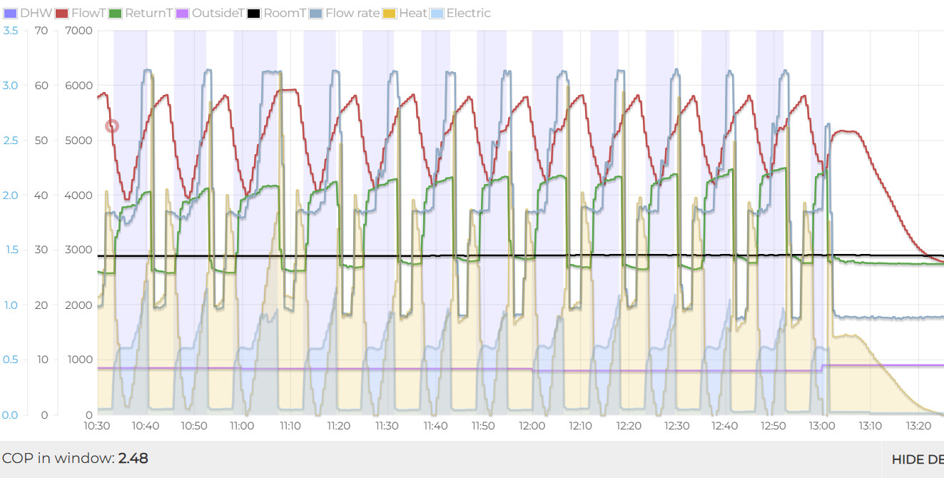
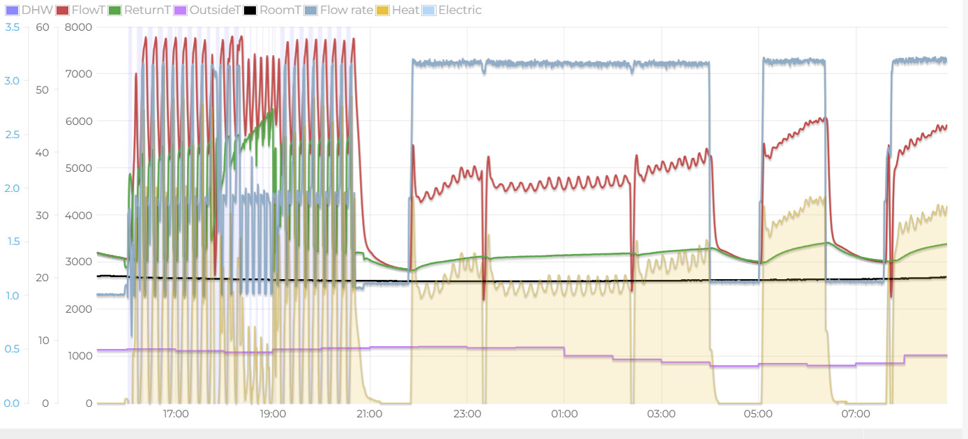
Your second graph is puzzling - apart from the confusion over the DHW mode - since the Return temp (Green) doesn’t appear to mirror the Flow temp (Red). Please could you clarify where those Flow and Return values are sourced from: is there a Heat Meter connected to the emonPi, and do the readings come from that?
A few other details about the system would be useful:
What’s the kW rating of the heat pump?
Which WC curve is selected and are there any ‘offsets’ applied?
Is the DHW side of things generally working OK? Does the DHW tank get hot when it should?
The NuHeat schematics allow for UFH with the option of radiators too. Are there any radiators present and roughly how many UFH zones are installed?
Its a 2050 10kW unit; no doubt over sized as it was selected based on MCS calc.
Weather comp curve 1, with a minus 10 offset (ie as cool as possible)
The tank warms but is 46C which isn’t as hot as I would expect (think it was set to 56C for a period of heavy loading- looking at it now I suspect this is causing the cycling that it is actually stuck in Luxury hot water mode)
There are about 5 UFH zones and one rad zone
I have myuplink running so I do have insight.
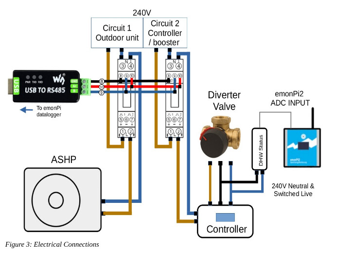
Parameter s1 I cant find that explicitly but can find “Calculated supply climate system 1” this shows that the target flow temp is very low around 22C.
Thanks for the extra info and the graphs from myUplink. Having the Hot Water set to ‘Lux’ mode without a correspondingly high usage of DHW could certainly explain the frequent-but-brief high temperature runs (and the lack of alignment with the heating(?) return temperature).
You’ve found the correct parameter for ‘S1’ and the values for that do align with being on a very low WC curve setting
There are some fairly high-temperature peaks on the BT25 External Supply Line Temperature chart, but perhaps those are just as a result of the diverter valve switching over at the end of a DHW cycle, which is normal behaviour for a NIBE unit
The Degree Minutes are tracking how much - and for how long - the BT25 value was lower than the S1 Calculated value.
By default, NIBE units will Start the Compressor (for a Heating cycle) when the DMs reach -60 and then Stop it again when they rise to 0
When the DMs are at +100 that means the heating demand was fully satisfied and that in fact the heating circuit was ‘too hot’
The controller limits the DMs from rising above +100, which is why there’s a flat line across much of the graph
Some other NIBE users have been seeing DMs go highly-negative (e.g. -800) which is a sign than the heating demand is present but is not being satisfied - but you’re seeing the opposite
So, in summary, the Heating side of things looks OK to me - which is consistent with the unit trying to do Hot Water rather than Heating.
Below a plot showing with ‘Luxury’ hot water ON then OFF. The difference is “night & day”. Just goes to show check the simplest explanation first (settings) before jumping to more involved diagnoses.
We can focus on fine tuning now. Thanks for your help