Hi All,
I admit I have done quite a lot of reading of forums and resources at this site and its left me fairly confused.
I would like simply a suggestion on which hardware to buy.
My need is that of monitoring water gas and electricity consuption and get live data feed remotly.
I’m going to renovate the house and at least for water and gas I will install new meters, which, from what I understand, must be predisposed for the pulse sensor.
As for electricity instead, my meter is too far from any monitoring station, so I think it will be necessary to use a CT sensor near the input box (220V, I live in Europe).
Can I use EmonPi to monitor water gas and electricity?
Would you be so kind to provide me a list of items I’ll need and I can buy to monitor my household utilities?
No, not all 3 on its own. The emonPi can measure electricity plus one pulse input, therefore you must have something else to measure the second pulse.
But first, check that the meters you intend to buy have either terminals for a pulse output (“S0”), or a rotating magnet inside which you can sense with a magnetic reed switch.
The most economical choice for the second pulse input would be the emonTH. Although it is an environmental sensor for temperature and humidity, it has terminals to accept a pulse input. It is designed to be powered by batteries, but you can also use a 5 V d.c. power supply if you wish.
Do you want to measure your total electricity consumption, or is it possible that in the future, you might want to measure individual circuits? The emonPi has inputs for two current transformers, but if you are likely to want more than two, then you should think about an emonBase plus emonTx plus emonTH. That combination would give you 4 current measurements and two pulse inputs.
Therefore, for what you asked for, to measure 1 electricity and 2 pulses, I recommend:
1 - emonPi
1 - a.c. adapter with Euro plug
1 - YHDC SCT-013-000 current transformer
1 - emonTH
either
1 - 5 V USB power supply for the emonPi with USB cable
or
2 - 5 V USB power supplies, for the emonPi and emonTH with USB cables
If you think you might want to change the firmware in the emonTH, then you will need a programmer. (You should not need it, but it is useful to have and you might want to buy this now, to save postal charges later.)
No, and I think I was wrong when I advised you to have an emonTH. I think (@pb66 will, I hope, help me here) you can use your emonPi to read two pulse inputs, if you are prepared to use the GPIO interface on the Raspberry Pi inside your emonPi, and install a script to read the pulses there.
If you use the pulse inputs only, you will need neither the a.c. adapter nor the c.t., and if Paul confirms that you can have two pulse inputs, you do not need the emonTH nor its 5 V power supply.
And I would buy this instead of the gas probe.
You can indeed, the example script used in the Directly connecting to Optical Pulse Counter with RPi? thread can be used on any Pi and theoretically use any number of unused GPIO’s on the Pi so you could have a dozen or so on a standard Pi, things get squeezed a little when you have an emonBase due to the RFM2Pi occupying or obscuring several of the GPIO pins, and things get a little tougher again with the emonPi as the add-on board occupies (but doesn’t actually use) all of the GPIO pins and the case might need to be drilled or cut to allow the additional wires to pass.
My experience of pulse counting has shown very little difference between optical pulses and S0 pulses once the conns are made, so I believe, you could also use an emonTH connected to the S0 contacts of the elec meter if you so desired, that could run on batteries at the remote meter and possibly reach the emonBase/emonPi and the S0 counting should mean the batteries last longer as there is no LED or additional electronics to drive.
Thank you Robert, Paul.
So basically I need a Raspberry PI with Emoncms on it and a couple of reed sensors to count each pulse and send them to the emonhub, is it right?
If so, I’ll try starting with a raspberry that I already have and one reed sensor, and then gradually I’ll make the system more complex. The only unknown is how far I can go with the GPIO pins… but I’ll stay under 5 meters, so it should be ok.
I would say reed switches are a backup alternative method for when S0 (volt-free) or a led pulse isn’t available. Either of these methods will be easier to implement and possibly be more accurate too. When choosing your meters, try to get ones with a pulse output if possible (either S0 or LED) it will make things much easier.
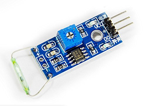
I bought a couple of reed switch sensors, reported to be compatible with the Raspberry Pi which works both with 3v and 5v (Unfortunately I did not find much information about it).
I’ve wired the sensor to the RPI as follows:
VCC to the physical pin 1 of the rpi (3v output)
GND to the physical pin 6 of the rpi (GND)
D0 to the physical pin 18 of the rpi (GND) (GPIO 24)
I simulated a series of pulses by passing a magnet near the sensor and thanks the @pb66 python script I could read the pulse, send the information to the emonhub and see the data on a chart.
Now the next step would be to use real sensors to get real data.
As already mentioned, I would like to measure the consumption of water, gas and electricity.
Now from what I learned, If I buy a meter with a reed switch I can’t directly connect the sensor to the raspberry as there is a limit to the applicable voltage and current to the gpio pins.
What options do I have?
Can I use the reed switch boards that I bought (above) to interface with the meter’s reed switch?
On all the meter technical specifications I found on the market there is reported only the maximum operating current and voltage for the reed switch, but not the minimum. Do they work with 3v output or I need some volt convertion?
What is the difference between reed switchs and S0 output which pb66 suggests?
Do S0 output can be wired directly to the rpi gpio?
No, the switch is not a voltage source. If in doubt, check with meter’s data sheet. If it shows a switch symbol going to two terminals and no connection to elsewhere, or if it mentions “volt-free”, then you don’t have a problem. You define the voltage you use. If you take the Raspberry Pi’s 3.3 V as the voltage source, it should be fine.
I don’t know what that interface does for you, but it looks overly complicated. If your meter has a reed switch, then you could probably use that interface. If it has something that behaves like a switch but isn’t (see what I’ve written about S0 outputs below), then it might not work.
There is no specific minimum, but you can have reliability problems if there is insufficient current to keep the switch contacts clean. The normal value of pull-up or pull-down resistor should be fine.
An S0 output behaves as a switch contact - so essentially there is no difference. In reality, it may be a semiconductor switch - a transistor - which is sensitive to polarity and which needs a minimum voltage applied to it. The data sheet for your meter should give details, it will say something like “5 - 30 V, 20 mA max.”
Probably, if it will work down to 3.3 V. (If not, you will probably need to use the 5 V supply and divide down the voltage that you apply to the GPIO pin.)