I’ve received my emonPi Solar today and I’m excited to start monitoring my solar and electric usage, but I cannot fit the CT sensors around any of the external the cables supplying my mains, or the ones that come from the solar inverter - they are simply too tight/close together.
I could place the CT sensors inside the Consumer Unit (obviously I’d isolate the supply first) - but would that be safe to do so, and would that work accurately?
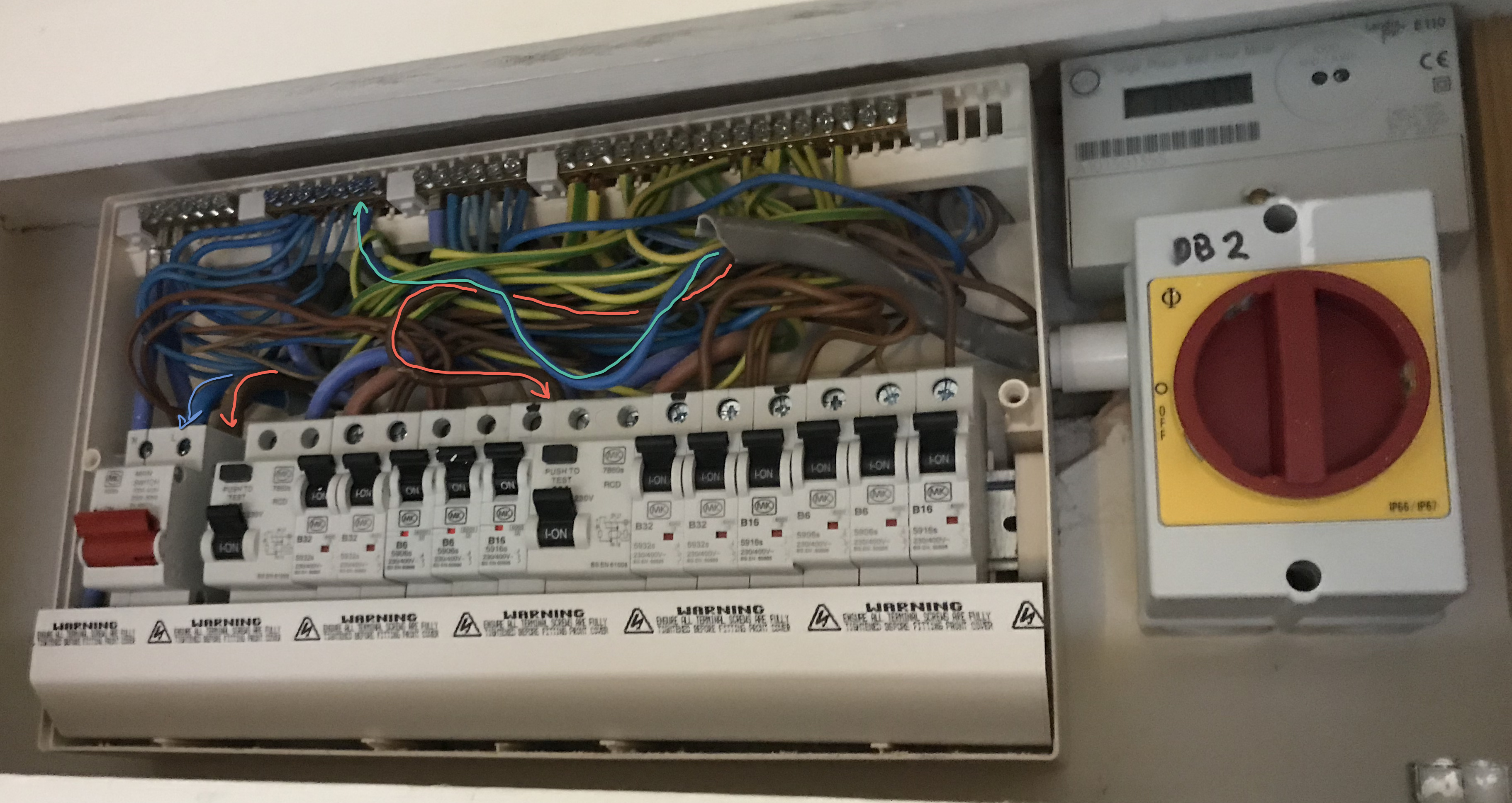
If I do place them inside the CU, which cables should I put the sensors on - the live from the supply, and the live from the solar inverter? (see red lines in the image)
Is that the grid meter or the generation meter that I can see?
I think you’re going to struggle to get the standard 100 A c.t. in there - even just one. Adjacent current-carrying cables do have an effect, it’s not major. A touching (but outside the core) cable carrying 100 A gave an indication of 160 mA in the c.t. So something to be aware of but not a major worry, I’d have thought. Strictly speaking, there should be a barrier between the cables at 240 V and the c.t. cables, but that’s hardly practical in there.
If you do need to get two c.t’s in there, you might be able to use a ring-core (rather than split-core) of a lower rating, that will therefore be physically smaller, on the PV infeed. And there’d be no harm in stripping that T&E back further (you need a bit more earth sleeving) to give you more of the brown core to play with.
You could look at the YHDC SCT006. This used to be stocked in the shop, that would be OK on the PV infeed. But it has disappeared, though no doubt it’s available elsewhere.
If you use (almost) anything other than our standard 100 A c.t, the emonPi will need special calibration on that channel, and that brings its own problems.
But you can’t do the same with the grid connection. Presumably, you can’t get at the tails between the supply fuse and the meter? Would I be right in thinking there’s a meter box on the other side of that wall? That would be an alternative place for the Grid c.t. If you can’t do that, you might manage to make some space at the left-hand end, by moving cables around.
And you do have a “Type 2” system (because you can’t measure the total house consumption on its own, without the PV contribution).
Yes, you can see the generation meter in the pic, and you’re correct, the meter box is on the other side of the wall, but about 2 meters lower. The problem with putting the CT out there would be drilling a hole through the exterior wall and extending down there, which is probably a bit drastic for my liking!
I’ve managed to get the packaged CT round the grid feed and though it’s not ideal (touching the neutral sleeve) it seems OK. Getting a ring core on the main feed would make me nervous (disconnecting it etc). There’s space above it’s current position for the CT to fit in the cover, so I can live with a little interference I think.
The PV feed is easier to get the CT on but not so easy to fit inside the cover once it’s on, I think I’ll need to strip back the sleeve as you said to get it more comfortably placed.
No, you must not do that - unless you’ve got an upstream isolator you can use. The electricity provider won’t be pleased if you break their seals and remove the main fuse.
It isn’t the voltage that would worry me, it’s the fault level that the supply fuse can carry while it’s in the process of rupturing. That would make a significant mess, and you’d likely be splattered with molten steel and copper. It wouldn’t be a good day.
That’s why I only suggested a ring core c.t for the PV infeed. You can safely isolate that.