Newbie: Measuring 3phase Voltages

Hi guys, I’ve watched this project from a while, first of all I want to give my congratulations to every one who puts their grain of sand to build such a big and interesting project.

I’ve worked in something similar to this (power monitoring) and emonlib has been helpfull with my particular work.

I don’t know if my doubt belongs here.

I’ve read here (somewhere, a while ago) that it is not possible to measure 3 phase voltage with one device, but I read it after I develop my own setup and the code to measure 3phase voltage, and it works “well”, because when a phase is not conected it drops the other two phases measurement.

Let me explain how I made my device

Its feeded by a switched power supply, so the GND and VCC has no galvanic continuity with AC inputs.

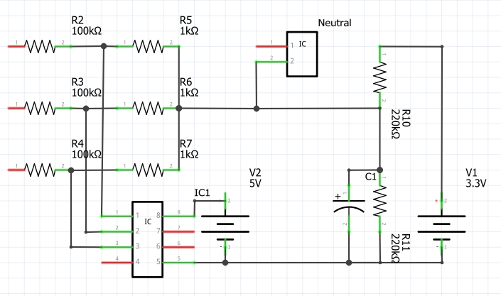
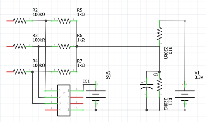
Was made with a nodemcu and a 8ch 12bit ADC, using 3.3v as reference, and a voltage divider to set the neutral of power grid at 1.65V in the device (3.3V— 220k - x - 220k —GND, where neutral is connected to “x” point).

A voltage divider of 100k and 1k is by each phase (phase — 100k ---- 1k ---- neutral <at 1.65V>), and ADC measuring voltage at 1k resistor.

A voltage divider to each phase to get aprox + - 1.5V peak (on 120VAC system) of sinusoid excursion (for positive and negative semicicle).

Yes maybe I’m crazy by not using a voltage TX but I think it is not necesary if everything is handled very carefully.

I didn’t use emonlib, but I used some lines of the library, thanks again to the community.

There is a behavior that is very particular, on phase 2 there is a over measure (about 5% of voltmeter value) meanwhile phase 1 and 3 measure ok (according the voltmeter and the theoric calibration factor estimated for this combination).

If a phase is not connected, it shows a 3v (even if its attached to neutral) and the other two drops around 100V.

My question is… Why is it not possible to measure the 3 phases with the same device?

Thanks in advance, hope to don’t bother you with my doubt and sorry for my bad english.
Don’t worry about your English. I know one English person who doesn’t write it anywhere nearly as good as you do (and he’s distantly related to me by marriage :frowning_face: )

Probably, what you read was “The emonTx cannot measure 3 phase voltages.” That is because it was designed only for the domestic UK system, which is almost exclusively single phase.

I have to say this: Never under any circumstances should anyone copy this unless they are qualified and experienced in working on live equipment, and fully understand the dangers.

As you’ve said, if everything is done very carefully… That is a very big IF. It is not just you who has to do everything correctly - what if there is a fault in your electricity supply? It’s quite possible that everything will then become live.

I would need a complete circuit diagram to give a definite answer that. My guess is the disconnected phase measures 3 V because it is measuring noise, very possibly coming from your switched-mode power supply.

Do you have a 4-wire system (L1 - L2 - L3 - N) or a 3-wire (L1 - L2 - L3), not counting the protective earth?

Is your star point (the junction of the three 1 kΩ resistors and the “GND” for your ADC) connected to the neutral of your supply system? If it is not, then the reason the other two phases read about 100 V is simple:
Your phase voltage is 120 V, therefore your phase-phase voltage is 120 × √3 = 208 V.
Your star point is on a voltage divider made up of 4 resistors ( 100 kΩ - 1 kΩ - 1 kΩ - 100 kΩ ) so it sits exactly mid-way between the two lines.
Each input then measures 208 ÷ 2 = 104 V.

Thanks for your quick response!

I have experience and know the dangers, so it was made very carefully, thanks for the advice, working with this systems never is extra to give safety recomendations, thank for it.

My system is 4 wires plus earth, and the center of the star is not conected to ADC´s GND, is connected to a 1.65VDC step (to measure positive and negative values around the DC step)

I know that the switched power supply introduces noise, but if its nothing conected it measures around 0.5V, the noise comes when is one phase connected

I´ve attached an image kind of my circuit, the IC is the ADC, powered by 5VDC, lets assume the power source is pretty stable, I know that a switched power supply introduces a lot of noise, but I´ve tried to sort it by other ways and I have a clean 5VDC and 3.3VDC power supply for this stage.

Thanks in advance

Yes, of course - I had not drawn it, I was trying to keep the circuit in my head. A bad mistake. :wink:

OK, then the low reading when one phase is disconnected is exactly as I wrote: It will read 104 V. If you draw the vector diagram, you will see why.

The 3 V is probably coming from the other two phases, via stray capacitance between the input pins of your ADC. When one phase is disconnected, the star point and the disconnected phase still have 104 V between them and either connected phase.

You have an 8-channel ADC. Can you put the 3 phases on (say) pins 1, 3 & 6 and ground pins 2 & 4? Having a grounded pin to shield the active pins from each other might help, if it is possible to do it. If you are making a printed circuit board, then a ground plane and guard tracks is the correct solution.

Well they are as you say at pins 1 3 and 5, at pins 2, 4 and 6 I have current inputs, and it doesn’t have noise at current pins (I guess is a win due the effect you mention).

I’m sorry, I forgot to draw that neutral is connected to center of star, theoretically it should measure 120V between any phase and neutral.

There is the corrected circuit, thanks for your quick response.

But what is “IC” that is connected there? For you to measure each phase to neutral voltage correctly, your star point must connect to the mains neutral directly.

My bad, it is just for illustrative purposes, the neutral wire is connected directly to star center.

I’ve done the schematics with frizing, and it didn’t allow me to put a wire “to air”, that’s why I added a component to illustrate where the neutral is connected.

Thanks.

I cannot see a reason for the wrong voltages, other than interference between the channels.
This could come in any number of ways, capacitance between adjacent tracks of your circuit board, current in one track inducing a voltage in another, currents flowing in a shared resistance (a pcb track for example), etc.

One thing to look carefully at, is the voltage of your 1.65 V bias stable, or does it have some of the mains signal on it? If it does, which will be when only one or two phases are connected, reduce the values of R10 & R11 to say 10 kΩ and increase the value of C1, or consider using an op.amp. to provide a low impedance source for the bias voltage. See Learn→Electricity Monitoring→Current & Voltage→5. Buffered Voltage Bias→Buffered Voltage Bias

I will try changing R10 and R11 to lower value, also I’m going to code to measure each chanel separately, because is very particular that phase 2, has the bigger error, don’t know if it makes sense, or if the ADC has a particular condition (I just worked with MCP3208, haven’t tried other else)… I’m not a deep electronic smarty

I already tried with an op. amp. (lm358) and it didn´t gave me satisfactory results, for current measurement it gave me around 500mA of noise (in stand by) with nothing connected, meanwhile using resistors (220k) and a capacitor (10uF) for each chanel it gives around 70mA of noise (thats pretty cool!), all for a 100A current sensor (100A:50mA version), using same power supply and circuit.

Thanks for your support @Robert.Wall, if I can achieve something, I will post here.

You could try a small capacitor on the output of your op.amp. They have been found to oscillate, which generates a lot of noise.

Have you seen sections 6.4 & 6.5 of the Data Sheet for the MCP3208 - about layout and grounding?

If you have a spare ADC input, you could try measuring the bias voltage (as if it is an input) to determine the error due to a mains frequency ripple on it.

Thanks for your recommendations, honestly I have not seen the datasheet in detailed way (my bad), thank you for remind me the basics when something is going wrong.

In same way, I will apply datasheet’s recommendations and post results.

Thank you again.

By using a transformer for each phase, this PCB of mine can provide accurate measurements of the voltage and current for each phase of a 3-phase supply. It uses the same Atmel 328 processor as the emonTx.
https://mk2pvrouter.co.uk/61101.html

And that is something the emonTx is not capable of, but which @ega’s system should do.

Sorry for the delay, was busy in other stuffs and after I could dedicate time to this.

Thanks @calypso_rae, but that’s what I want to avoid, the need to use TX for size reasons, meanwhile smaller is easier to install in any cabinet.

@Robert.Wall I solved the issue… There was a broken link between neutral and the DC step that I’m using as reference, I installed a wire bridge, and now it is measuring ok, when there is a voltage terminal to air (not connected) it measures 1.3V, and the other two phases measures 118V (the same measure when the three voltage terminals are connected), and when I attach it to neutral measures 0.35V (other two phases remains 118V), I know that it should measure a big 0, haven’t applied the recomendations of your previous post, but at this point I’m satisfied with the results.

Thanks again.