Hi there. I’m sorry if this question has been asked before, but I’m guessing every installation is different so want to be absolutely sure I get what I need.
I have a property with a 4kW solar PV array and a 15.2kW Ochsner ground source heat pump. I would like to get a better handle on my energy generation and consumption (particular the GSHP) patterns in order to optimise my usage, and give me better data for making decisions about energy suppliers/tariffs. Ideally, as I don’t currently have a solar PV diverter, I’d also like to investigate ways of diverting excess generation to the immersion in the DHW tank to reduce the amount of work the GSHP needs to do.
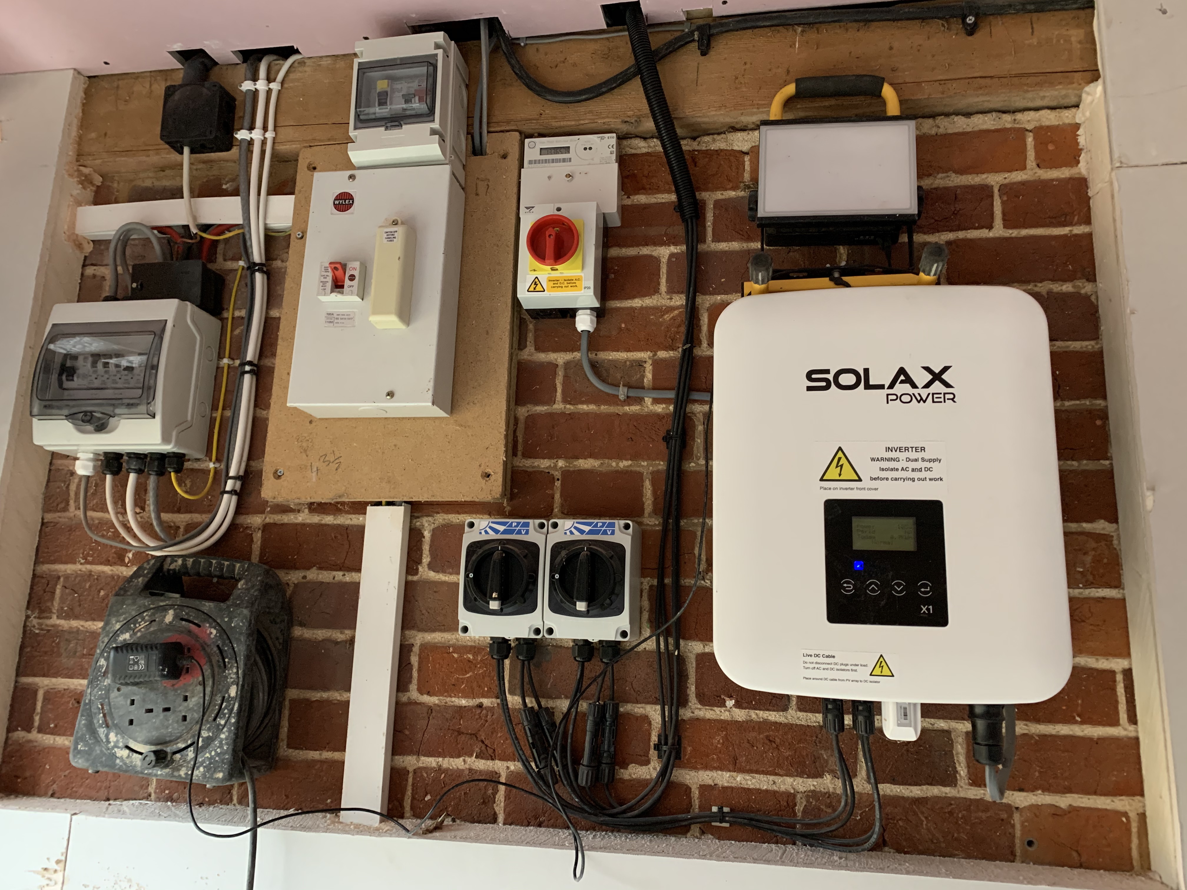
The incoming feed from the external meter box enters the house on an outside wall and goes on to feed the main consumer unit. However, the solar PV inverter, generation meter (no export meter), and consumer units for the GSHP and PV are all located together (as per the photograph). The GSHP itself is about 6m away from this location, and consists of the heat pump and two buffer tanks (UFH/Rads and DHW) with mixing valves.
What I’m trying to get my head round is what I would need for this set up. I was initially assuming an emonPi Solar PV Bundle installed near the solar inverter/incoming feed, but I’m not sure whether this would be sufficient (and whether I’d need an optical pulse sensor on the generation meter), and how I would then address the PV diversion.
It looks like an EmonTx with 4x CT inputs coupled with an emonBase could be the best approach in your case. You could then monitor the Import/Export, Solar, Heatpump and then potentially a diverter when you get one all from the same unit.
To use the CT sensors you will need to be able to clip around either the live or neutral cables (insulated) for each of these circuits. It looks like at least the grid import/export might be available in this way in the top-left of your picture.
You may wish to get an electrician to install the CT sensors if needed inside the trunking, it’s hard to see exactly from here where you need each sensor installed.
Thanks @TrystanLea for the welcome and quick response. Funnily enough, I was just looking at the emonBase and emonTx and wondering why I wouldn’t go with that option.
Access to the live or neutral incoming feed shouldn’t be too difficult (they come up inside the vertical trunking at the bottom left of the photo).
The PV circuit might be more tricky as I’m assuming I’d need to install a sensor on a single live or neutral wire in the grey cable that runs from the inverter to the red isolator switch just below the generation meter. Is there any reason I couldn’t use an optical sensor on the generation meter to measure the PV circuit instead of a CT clamp?
Can you access the cables on the other side of the generation meter? (The meter itself consumes very little power, so it won’t materially affect the readings.)
You can use the optical pulse counter for the generation meter - the main reason for recommending a c.t. instead is the pulse only happens after the event - after a specific quantum of energy has been generated - whereas a c.t. will give you continuous data contemporaneous with the other c.t. inputs.
Hi @Robert.Wall. By “other side” I assume you mean between the generation meter and the fuse box? I can, but as with the cable between the inverter and the meter, it’s a fairly thin three core cable so I’m assuming I would need to break into it and isolate the live or neutral?
In the photo it’s the grey cable at the left of the bunch of grey and white cable and going into the fuse box far left (white plastic entry gland).
Yes - that is what I meant. I wasn’t able to follow the route of the cable, so I had no idea which it was.
I’d be inclined to get a plastic box big enough for the c.t. and maybe a strip of terminals, a couple of glands and break into either that cable below the consumer unit, or the cable between the inverter and the a.c. isolator, putting the c.t. inside the box where the split cable (minus the protective grey sheath) would give you access to the cores whilst protecting them against physical damage.
I doubt that there will be enough room inside the c.u. for a c.t.
Not at all. In theory it should be centred in the aperture, in practice, it’s very difficult to measure the difference. On thing you must never do is clamp the c.t. onto the cable. The core is ferrite, a very brittle material, and any pressure on it will result in it snapping, rendering the c.t. useless.
Thanks all. Very helpful. Final question, what functionality do I lose if I just go with the emonTx and the WiFi module rather than the emonBase (for now, at least)?
It’s fairly easy to split the conductors apart in a length of T+E and then put a CT around one conductor, without cutting any conductors. Practice on a scrap length of cable if you haven’t done it before. Clearly best to turn off the power whilst doing this and enclose the result to meet double insulation regs.
Note that a CT and an optical sensor on the meter don’t measure exactly the same thing, and each has their own errors and bugs. I have one of each for solar generation and still write down the meter reading each night as a backup.
The emonBase also runs emoncms so you have your own local logging history and display facilities. It also makes it easier to add another emonTx later if required.
I should just point out that the outer (in @Niall_Cook’s case - grey) pvc is not insulation, it is mechanical protection - which is why it has different mechanical properties to the real insulation which is the brown and blue coloured stuff. Of course, being PVC it does insulate as well, but that’s not its primary purpose.
I suggested putting the “damaged” part of the cable inside a box exactly for the reason that the box would provide mechanical protection:
I’m no expert,I was just using the term my electrician uses. I believe he uses it because the type of insulation/coverings we are discussing is defined as “double insulation” by BS7671 : 2008 Part 2.
I do agree that the primary purpose of the outer insulation is mechanical protection.
Sorry for any confusion, but the discussion between @Robert.Wall and @Niall_Cook involved a terminal block and so gave me at least the impression that cutting the conductors formed part of the process, so I wanted to make it clear that that was not necessary.
I was making a judgement from the photographs, and thought that there may well not have been enough spare cable to do the modification properly, neatly and safely without adding a piece of cable and using terminal blocks to make a joint.
Still going by the photograph, I would have opted to take the existing cable out of the a.c. isolator and put in a new piece, then I’d have as much spare cable as I’d ever need without stretching or risking damage to the insulation. You still need to pull the cable out to get it through the new glands and the box, so why make it hard for yourself?
I figured you had something like that in mind, but I’ve never seen that sort of JB that’s big enough to get a current transformer - especially a 100 A one - inside. The only way like that would be to use the bottom half of a box and fix it in somewhat Heath-Robinson fashion to the brickwork.
My electrician was out today doing the second fix on my office (in the same room) so I got him to sort me out a power socket and a box where we could split the cable between the PV isolator and the fuse box. I hope this will do the job (the incoming live is in the white trunking just to the right.