I’ve just setup three emonTx with the stock firmware (V3.4 Discrete Sampling V3.00) and AC-AC adapters from the store. The VRMS values reported by all three Tx are consistently higher. My multimeter reads around 231v and the Tx are reporting 255-258v.
Is this a case for calibration? Where should I start?
(only prior experience was with an emonPi, and it was reading the same VRMS as my multimeter, within 1-3v tolerance)
Are you using the same a.c. adapter for both, and which one is it?
The emonTx and emonPi have for some reason different default calibration constants, but that only explains part of the difference. The theoretical voltage calibration constants, which are the same for both emonPi and EmonTx V3.4, are:
For the Ideal Power 77DB-06-09 (UK Plug type) 268.97
For the |Ideal Power 77DE-06-09 (EURO Plug type) 260.0
For the Ideal Power 77DA-10-09 (US Plug type) 130.0
I stress these are the theoretical values. Component tolerances, especially in the a.c. adapter (±3%) will affect the actual value required to give an accurate reading.
The default value for the emonTx is for the UK adapter (268.97 or 130.0 in USA mode) and for the emonPi is 256.8 or 130.0
It is the same adapter, the “ACACEU” (77DE-06-09 Euro plug). I used it briefly on a emonPi, then moved it to the Tx, where I saw the higher voltage readings.
One thing worth mentioning: the emonTx is configured with the dip-switch in the “USA” setting, though I haven’t yet checked in the firmware what is the effect of this setting.
The local mains voltage here is supposed to be 220 Vrms, altough my multimeter consistently shows a value a bit higer, in the neighborhood of 230V. The emonPi was reporting a value matching what the meter reads, the emonTx is reporting almos 260V.
Over the weekend I will review the calibration procedure Bill linked to and perform some tests.
That’s easily explained - in part - by the different default calibration constants.
If you’re running the EU adapter on 220 V, the “USA” setting is wrong - you’re effectively saying that 9 V out (actually, it isn’t, it’s closer to 11 V, but the argument holds true) represents 120 V mains whereas with the UK/EU setting, it represents 240 or 230 V respectively.
What I can’t work out is how that gives you 260 V, it should show something like 110 - 115 V.
The calibration details:
The EU adapter is 230 V in, 11.5 V ±5% out (at 50 Hz). What it will be at 60 Hz, I don’t know. But it won’t be very different. That is divided down inside the emonTx in the ratio 1:13 and fed to the ADC. Those resistors are ±1%, the error in the divider might be about 1.2%. The calibration constant is the mains voltage that would give you 1 V at the ADC input, (not the actual voltage) so for you, it should be 260. You could expect to change it by up to ±6.25% to get the correct reading.
All this is assuming you don’t have a fault in your emonTx - all three? - unlikely.
As a first step, set the DIP switch to “not USA”.
Next, comment the voltage calibration constant “Vcal” in line 99 and uncomment the one for 260 2 lines below, and delete “const” at the start of the line.
Check what the result is - it should be closer, and then if necessary do the calibration procedure.
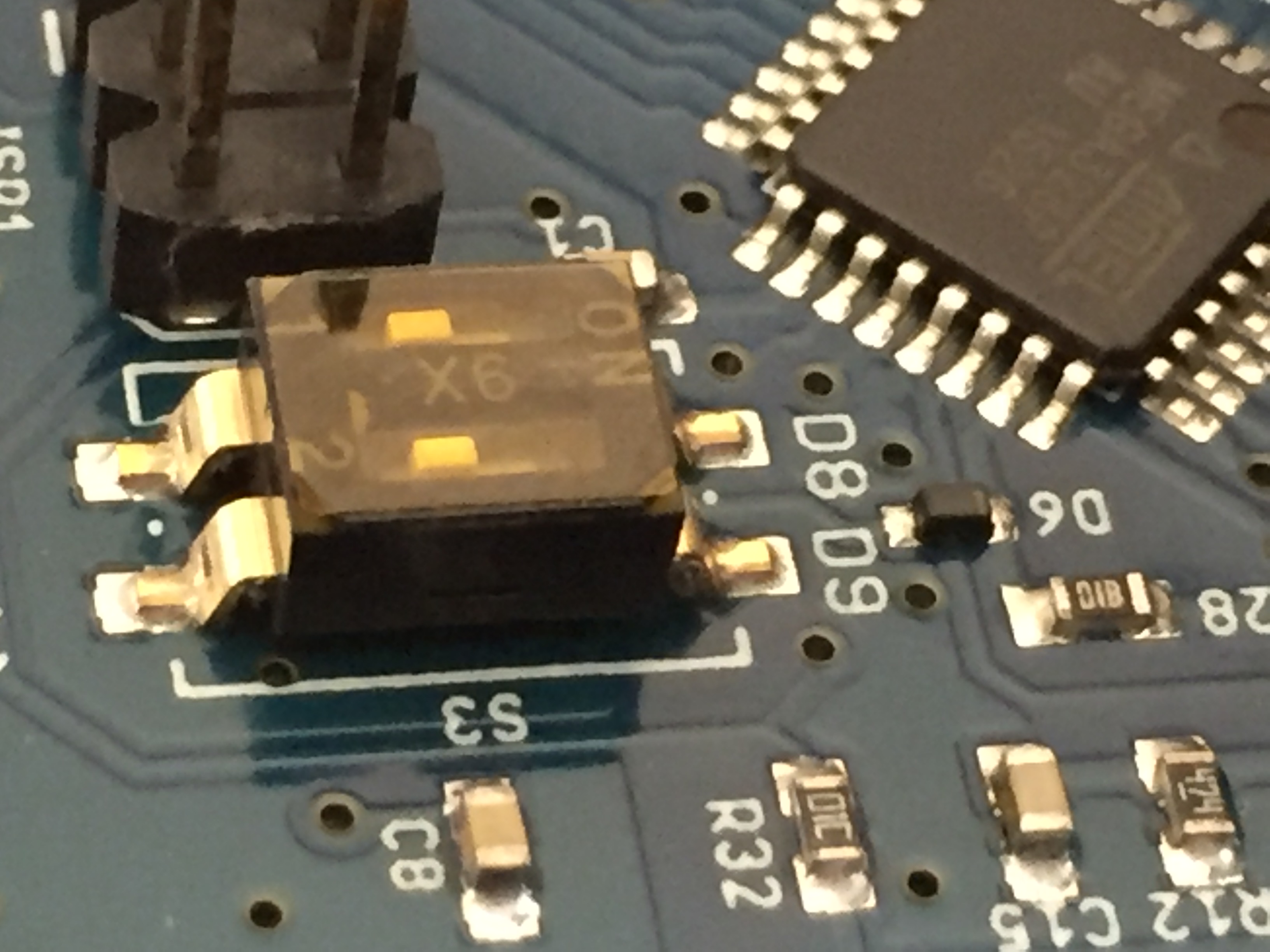
there’s a yellow-ish film covering those dip switches. Just peel it off with your fingers - the DIP switch you can set with the tip of an old pen, screwdriver or similar.
Oops, my bad! I inferred that it was in “USA mode” because I saw the string “USA” in the serial output. What I actually saw output was “USA 0” (meaning “off”), which I understood after looking at the code.
So I’m back to having to play with the constants in the code, which will take a while because I need to first get my serial cable in better shape, what I have right now is too clunky …
So it isn’t in USA mode,but why is the calibration so far out? The resistor divider tolerances (~1.2%) plus the difference in calibration constants (+3.35%) don’t account for the 231 V reading as ~256 V (+11%) especially as Claudio has used the same a.c. adapter, which is within about 1% when used with the emonPi.
And there are three, all reporting high voltages with that adapter. Could there be a batch with a wrong resistor?
I’ve unplugged all three AC adapters and measured the secondary voltage (open, without a load). All three read 11.2v +/- 0.05v, for a mains voltage of 229v.
I gave you the data sheet values earlier for 50 Hz, which are 230 V in, 11.5 V ±5% out (at 50 Hz). Scaling those to your 229 V, you expect 11.45 V, which means yours is low by 2.18%. It is easily within tolerance, so you cannot complain.
That is good to know. It removes any doubts about the accuracy of the a.c. adapter (though as you had used the same one with the emonPi, that was always unlikely).
Let us see what your voltage calibration constant is after you have gone through the procedure. It ought to be 265.80 ( 229 ÷ 11.2 × 13 – the “13” is the resistor divider ratio inside the emonTx).
Note that the calibration takes into account variations in the sensors as well as the components inside the emonTx, so once calibrated, each sensor has to stay with the input that it was connected to during calibration.
Makes sense! (and I did forgot about your earlier comment on the spec for the transformer ). I will update this thread after I go through the calibration procedure, although that may take a while …
Thanks a lot for all the support so far, I’m learning quite a bit in the process!
Quick update from my end here: managed to get a better connector in my serial-usb cable, matching the pins in the emonTx, so not I don’t have to remove the face plate in order to get a serial terminal going
Before performing calibration, I want to make sure I can load the latest firmware (I’m running 3.0.0, trying to upload the latest from github, 3.1.0)
Here’s where I’m stuck:
I’ve installed platform.io and compiled the firmware just fine
Ran the upload procedure, it finds the right serial port and opens it without issues (I can tell this step is working because if I have a terminal open on the serial port while attempting to upload, I do see errors in the pio output)
When platform.io tries to update, it tries 10 times, but complains that the “programmer is not responding”
If I reset the emonTx while pio is trying to upload, it immediately aborts.
In the console output pasted below you can see that I waited until attempt #7, then I hit reset in the emonTx
It is worth noting that I’m running this on a Windows 10 64b box, with Python 2.7.14; I did find some references to this error pointing to udev rules, but that appears to be a linux-specific issue.
Any thoughts?
$ pio run -t upload
Processing emontx (platform: atmelavr; board: uno; framework: arduino)
----------------------------------------------------------------------------------------------------------------------------------------------------------------------------------------------------------------------------------------------- Verbose mode can be enabled via `-v, --verbose` option
CONFIGURATION: https://docs.platformio.org/page/boards/atmelavr/uno.html
PLATFORM: Atmel AVR > Arduino Uno
SYSTEM: ATMEGA328P 16MHz 2KB RAM (31.50KB Flash)
Converting src.ino
Library Dependency Finder -> http://bit.ly/configure-pio-ldf
LDF MODES: FINDER(chain) COMPATIBILITY(soft)
Collected 28 compatible libraries
Scanning dependencies...
Dependency Graph
|-- <EmonLib> 1.1.0
|-- <JeeLib>
|-- <OneWire> 2.3.4
|-- <EEPROM> 2.0
|-- <DallasTemperature> 3.7.7
|   |-- <OneWire> 2.3.4
Compiling .pioenvs\emontx\src\src.ino.cpp.o
D:/git/external_repos/emontx3/firmware/src/config.ino: In function 'void save_config()':
D:/git/external_repos/emontx3/firmware/src/config.ino:101:22: warning: comparison between signed and unsigned integer expressions [-Wsign-compare]
for (int i = 0 ; i < EEPROM.length() ; i++) {
^
D:/git/external_repos/emontx3/firmware/src/src.ino: In function 'int get_temperature(byte)':
D:/git/external_repos/emontx3/firmware/src/src.ino:555:1: warning: control reaches end of non-void function [-Wreturn-type]
}
^
Linking .pioenvs\emontx\firmware.elf
Checking size .pioenvs\emontx\firmware.elf
Memory Usage -> http://bit.ly/pio-memory-usage
DATA:    [========= ]  85.6% (used 1753 bytes from 2048 bytes)
PROGRAM: [=====     ]  52.8% (used 17042 bytes from 32256 bytes)
Configuring upload protocol...
AVAILABLE: arduino
CURRENT: upload_protocol = arduino
Looking for upload port...
Auto-detected: COM7
Uploading .pioenvs\emontx\firmware.hex
avrdude: stk500_recv(): programmer is not responding
avrdude: stk500_getsync() attempt 1 of 10: not in sync: resp=0x04
avrdude: stk500_recv(): programmer is not responding
avrdude: stk500_getsync() attempt 2 of 10: not in sync: resp=0x04
avrdude: stk500_recv(): programmer is not responding
avrdude: stk500_getsync() attempt 3 of 10: not in sync: resp=0x04
avrdude: stk500_recv(): programmer is not responding
avrdude: stk500_getsync() attempt 4 of 10: not in sync: resp=0x04
avrdude: stk500_recv(): programmer is not responding
avrdude: stk500_getsync() attempt 5 of 10: not in sync: resp=0x04
avrdude: stk500_recv(): programmer is not responding
avrdude: stk500_getsync() attempt 6 of 10: not in sync: resp=0x04
avrdude: stk500_recv(): programmer is not responding
avrdude: stk500_getsync() attempt 7 of 10: not in sync: resp=0x04
avrdude: stk500_getsync() attempt 8 of 10: not in sync: resp=0x00
avrdude: stk500_getsync() attempt 9 of 10: not in sync: resp=0x00
avrdude: stk500_getsync() attempt 10 of 10: not in sync: resp=0x00

avrdude done.  Thank you.

*** [upload] Error 1
========================================================================================================= [ERROR] Took 87.86 seconds =========================================================================================================

================================================================================================================== [SUMMARY] ================================================================================================================== Environment emontx              [ERROR]
Environment emontx_deploy       [SKIP]
========================================================================================================= [ERROR] Took 87.86 seconds =========================================================================================================
You might struggle for assistance specific to running PIO on windows, many of us prefer to use the Arduino IDE, Glyn (who advocates the use of PIO) doesn’t use or test on windows so help maybe thin if at all.
I notice it auto detects your device is on COM7, is that accurate (check your device manager)?
Before trying to upload firmware have you just tried checking the PIO console for serial output from your device? That would prove a working connection (or not, which is what those errors seem to suggest).
9 times out of 10, those errors point to the physical connections (power supply, poor/reversed Rx/Tx conns or no reset line) or incorrect upload baud.
Well, I did try pio because the level of detail on the readme file under firmware was much greater than with Arduino. But I will make an attempt with the Arduino IDE later today and report back.
Meanwhile, I can confirm that COM7 is the right port and that communication succeeds, as I can see the output logged from the device:
$ pio device monitor
--- Miniterm on COM7  115200,8,N,1 ---
--- Quit: Ctrl+C | Menu: Ctrl+T | Help: Ctrl+T followed by Ctrl+H ---
CT 1 Cal 90.90
CT 2 Cal 90.90
CT 3 Cal 90.90
CT 4 Cal 16.67
RMS Voltage on AC-AC  is: ~2V
AC-AC NOT detected - Apparent Pwr measure enabled
Assuming VRMS: 230V
Assuming power from batt / 5V USB - power save enabled
NO CT's detected
No temperature sensor
CT1 CT2 CT3 CT4 VRMS/BATT PULSE
ct1:0,ct2:0,ct3:0,ct4:0,vrms:500,pulse:0
ct1:0,ct2:0,ct3:0,ct4:0,vrms:500,pulse:0
ct1:0,ct2:0,ct3:0,ct4:0,vrms:500,pulse:0

--- exit ---
Got it, excellent guide and suggestion wrt organizing the libraries’ folder.
Using the Arduino IDE (v1.8.5) I can see the device output from the serial monitor, and I can compile the firmware sketch just fine. I cannot upload though, I get a very similar error (see below).
I wonder if I have to do anything special in order to put the micro-controller in programming mode, or if the bootloader should handle it all? My only other arduino experience is with the boards that have the USB-serial controller embedded, so I’m not sure if there is any special handshake going on …
Output of an attempt to upload the firmware: (board selected: Arduino/Genuino on COM7)
Sketch uses 17352 bytes (53%) of program storage space. Maximum is 32256 bytes.
Global variables use 1755 bytes (85%) of dynamic memory, leaving 293 bytes for local variables. Maximum is 2048 bytes.
Low memory available, stability problems may occur.
avrdude: stk500_recv(): programmer is not responding
avrdude: stk500_getsync() attempt 1 of 10: not in sync: resp=0x87
avrdude: stk500_recv(): programmer is not responding
avrdude: stk500_getsync() attempt 2 of 10: not in sync: resp=0x87
avrdude: stk500_recv(): programmer is not responding
avrdude: stk500_getsync() attempt 3 of 10: not in sync: resp=0x87
avrdude: stk500_recv(): programmer is not responding
avrdude: stk500_getsync() attempt 4 of 10: not in sync: resp=0x87
avrdude: stk500_recv(): programmer is not responding
avrdude: stk500_getsync() attempt 5 of 10: not in sync: resp=0x87
avrdude: stk500_recv(): programmer is not responding
avrdude: stk500_getsync() attempt 6 of 10: not in sync: resp=0x87
avrdude: stk500_recv(): programmer is not responding
avrdude: stk500_getsync() attempt 7 of 10: not in sync: resp=0x87
avrdude: stk500_recv(): programmer is not responding
avrdude: stk500_getsync() attempt 8 of 10: not in sync: resp=0x87
avrdude: stk500_recv(): programmer is not responding
avrdude: stk500_getsync() attempt 9 of 10: not in sync: resp=0x87
avrdude: stk500_recv(): programmer is not responding
avrdude: stk500_getsync() attempt 10 of 10: not in sync: resp=0x87
Problem uploading to board.  See http://www.arduino.cc/en/Guide/Troubleshooting#upload for suggestions.


 ). I will update this thread after I go through the calibration procedure, although that may take a while …