Negative values after switching to split-phase

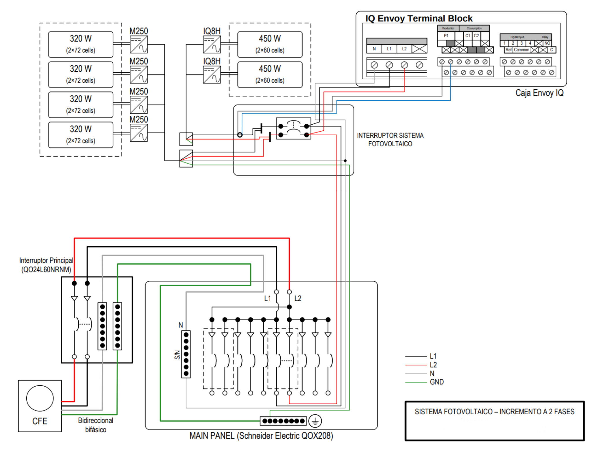
I recently upgraded my electric service from single phase (110V) to split-phase (220/110V). So I reconfigured my EmonPI to use the second CT in the second leg (previously I used it to monitor my solar panels).

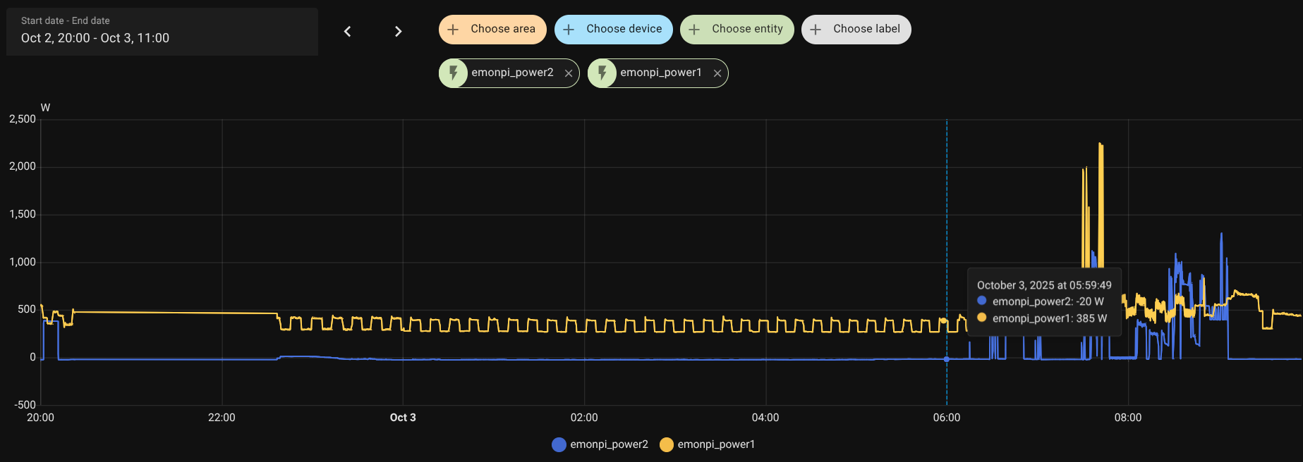
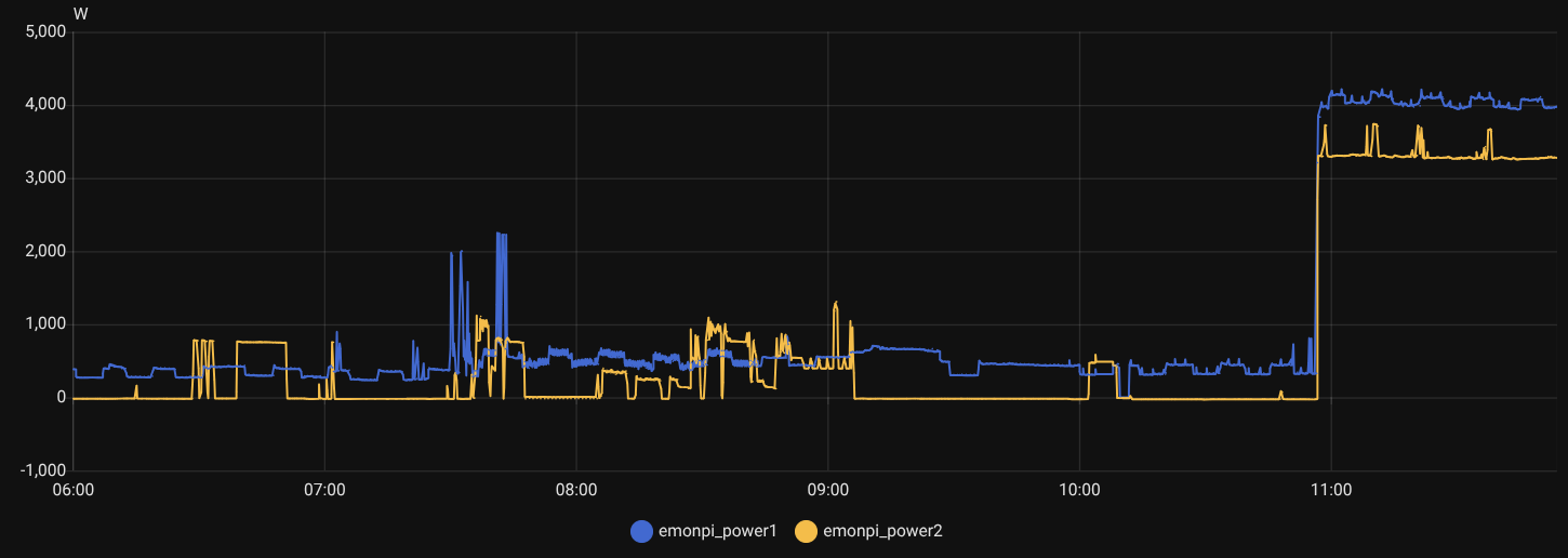
However, even with the photovoltaic system turned off, the second leg is showing a negative value when there is no load in that leg.

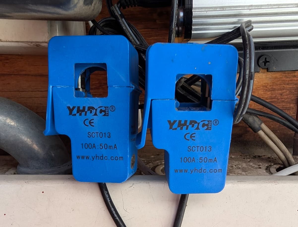
One CT (phase 1) is pointing towards the load and the second CT is pointing the other way. The voltage sensor (ACAC converter) is connected in phase 1.

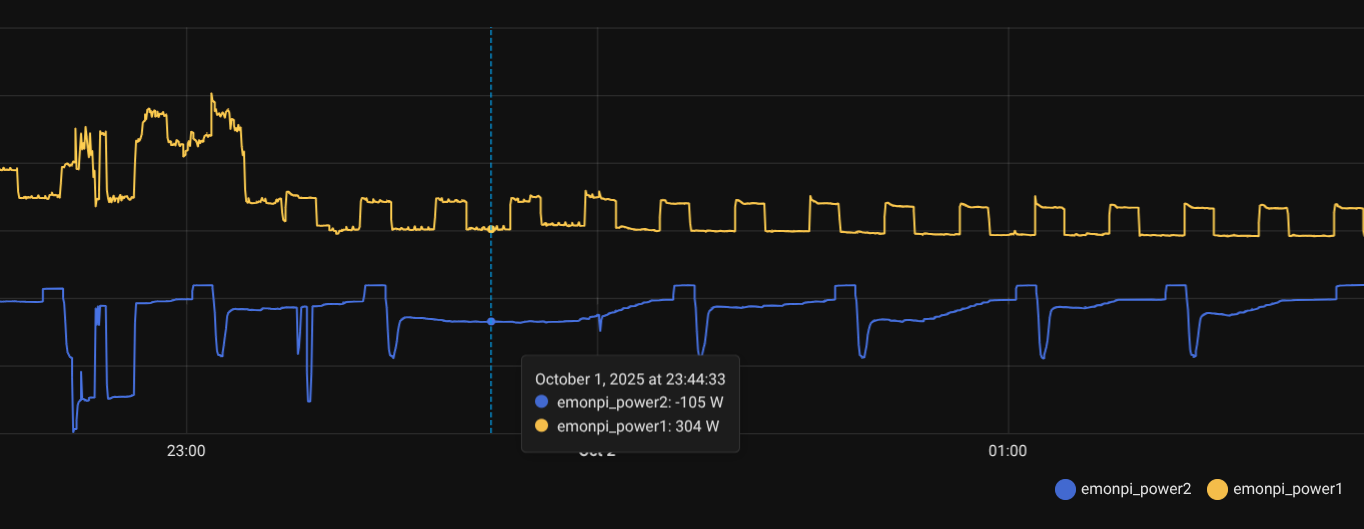
This graphic shows how CT 2 is showing a constant value of aroud -100W, with a strange behaviour during the night.

I am wondering if there is something wrong in my installation or if this is an issue on EmonPI (which I had since 2017 and has been working with no issues at all!).

I am using stock SD image 10-Nov-2022 (stable), but I upgraded the firmware to emonPi_CM 1.1.4, with EmonHubOEMInterfacer (which I re-compiled manually to adjust the Vrms value).

This morning I reverted to the previous firmware using EmonHubJeeInterfacer, but still showing negative values in phase 2.

You have what we now call the emonPi1. Was it the front end sketch or the EmonHubOEMInterfacer which you re-compiled manually? because changing the interfacer doesn’t make sense.

How are your solar panels connected? Are they 120 V connected to just one leg (which one?), or are they 240 V connected across both legs? Where was the c.t?

I can’t see the Y-axis on your graph, I don’t know what to expect, so it does not tell me much.

Your c.t’s should be positioned and connected according to this Use in North America — OpenEnergyMonitor 0.0.1 documentation, which from your description is what you have.

For a quick test of the emonPi itself, can you put CT2 alongside CT1 and pointing the same way? You should see the same current/power as CT1, and not negative, to within a couple of percent (especially at higher powers, at only a hundred watts or so, the difference will be much greater in percentage terms - maybe as much as 30 W, I’m seeing 34 and 53 W at present on an emonPi1 with both c.t’s on the same wire).

If it is negative, have you got a negative value for the current calibration of CT2, either in the sketch itself or in emonhub.conf, or a -1 multiplier somewhere in the Input processes of emonCMS?

If it’s positive, are you sure you had the c.t. on the correct wire?

It’s most unlikely. If you can measure the three voltages with a multimeter, you should read 120 V between each line and neutral, and 240 V line-line. If you genuinely measure only a few volts line-line, then there’s something seriously wrong.

As I would expect.

If you’d like to post your version 1.1.4 of the sketch (emonPi_CM.ino), I can check it against the original to see if an error has crept in somewhere.

Thank you Robert!

Regarding the emonPi_CM, I retryed using the stock version and then via the Serial Config menu, resetted it back to default values. Then I just applied voltage calibration to match my multimeter reading:

k0 139.1

How are your solar panels connected?

They are Enphase, so I had to use an autotransformer previously to convert 220V to 110V. When I got my electric service upgraded I just bypassed the autotransformer.

Here is the final diagram:

EmonPI’s CT are attached to L1 and L2 between the main breaker and the load center, the AC/AC adapter is connected to L1/N.

Yesterday I kept my solar system disconnected, during the night L2 was showing a constant negative value of about -20W (yes, the phases are heavily unbalanced, I’m working on that too!):

I performed the test you suggested (attaching both CT’s to the same wire), I got a slightly different reading.

Something interesting is: having both CT’s unattached, I got 0W on CT1, and -12W on CT2, so I think there is a problem there.

The CT’s I’m using are:

L1-L2: 220V
L1-N: 130V
L2-N: 120V

It seems to me CT2 is not working properly. Perhaps I can use the setting k2 and try to re-calibrate it?

This is not unusual. A current transformer is naturally inaccurate at very low power, and the 12 W you are seeing is most likely due to interference picked up from somewhere. Remember, those are 100 A c.t’s so the maximum power you can measure is ~12kW, so the error is 0.1% of maximum power - and the bad news is the c.t. accuracy is only quoted down to 10%, i.e. 10 A, or ~1.2 kW; it is ±3% from 10 A to 120 A, even though the emonPi cannot measure more than 100 A.

Don’t adjust the k2 setting to try to ‘correct’ the 12 W error. k2 will indeed change the calibration, but you should do it only when you have a large current that is resistive (electric heaters for example).

This tells me CT2 and the maths both in the “emon” part and emonCMS appear to be correct. So, I cannot explain why you saw a negative current overnight, unless it is very small and it is because your PV inverters (4 on L2) are essentially capacitors while they are not working and giving you a load with a power factor that is almost zero.

If this is the case, you have a comparatively high current almost 90° shifted from the voltage, giving very little real power. If the phase angle correction is wrong, then the current might appear in the wrong quadrant and it will be calculated as a negative power. Again, phase error is a property of the c.t. that is not documented by the manufacturer and gets worse the lower the current you are measuring.

So I understand I the CTs are too large for my current loads and this is a matter of expected error.

What I’m thinking as a workaround is to use Home Assistant to add some “bias” (something like +12W) to the reading so I can keep it in “0” when there is no load. What do you think?

When I have my EV charging, the values seems normal, as we can see in the following chart:

I’ll add a commercial energy meter just for comparision.

Thanks again!!

I’m afraid this is correct, and one of the reasons why we have moved to 0.333 V output c.t’s, which are available with a much wider range of rated currents, making them suitable for a much wider range of applications, and improving accuracy at the same time. Unfortunately, you can’t mix the new c.t’s and the old emonPi1, the input circuit of the emonPi2 is totally different to that of the emonPi1.

That is certainly a valid action. A better place to do this is probably on the Inputs page of emonCMS (though I know nothing of Home Assistant and it depends on where the data leaves the OEM hardware//software). Simply introduce a new first step in the process list to add the required value.

The error has been swallowed up by the 3 kW load. It will still be there, you can’t see it.

1 Like

That is definitely one of the characterisitics of Enphase microinverters.
My system (comprised of Enphase micros) has a PF of ~0.07 at night.

That’s interesting to hear! Actually the inverters are connected to both L1 and L2. Specifically, the M250s use the neutral line, while the newer IQ8H models connect only to the two line conductors.

I installed a Shelly Pro EM-50 today for an additional data reference, and I’ve found some potentially interesting results:

  • I’m seeing a significant difference in power factor (PF) between the phases: L2 has an extremely low PF (≈0.2), while L1 is ≈0.8.
  • It’s reassuring that the power measurements between the EmonPi and the Shelly device are quite similar.

I’m still struggling to draw a solid conclusion from this data. Given the large difference in phase measurements, I’m wondering if the utility company’s difficulty in connecting my second phase might be a factor. Could they have inadvertently connected the second line to a different transformer? That might explain the phase discrepancy.

I have no idea how the electricity supply is distributed where you are, I would have thought it extremely unlikely, and even unsafe. :worried:. By transferring your a.c. adapter temporarily to the other leg, you can easily check because the power factor should transfer with it (approximately).

Something is definitely not right here.

Your line to neutral measurements add up to 250 Volts, yet your line to line
measurment comes up 30 Volts less than the sum of your L-N readings.

Sounds like you’ve got a flaky neutral connection somewhere between your load center (circuit breaker panel) and the transformer feeding your house.

What time of day do you see this low power factor, at?

Here a screen capture of my system PF at a little after 11PM:

My system consists of M250 and S280 inverters.

I won’t say no, as stranger things have happened, but it’s not likely the second leg is connected to a different transformer.

If it were, you should be able to see said transformer, as it would not be far from your house.

Look at your Service Drop weatherhead. If you see a total of 3 wires going to the same transformer, then you know your newly added leg is on the same “pot” your original leg is on.

My electrical superintendent friend also said there’s a possibilty the transformer
itself is bad/causing the problem.