Greetings, first post here. Sorry in advance for the long post but I figured I would try to give as much info as I have available up front to help point me in the right direction. Please feel free to redirect this to the proper channels/forums where needed.
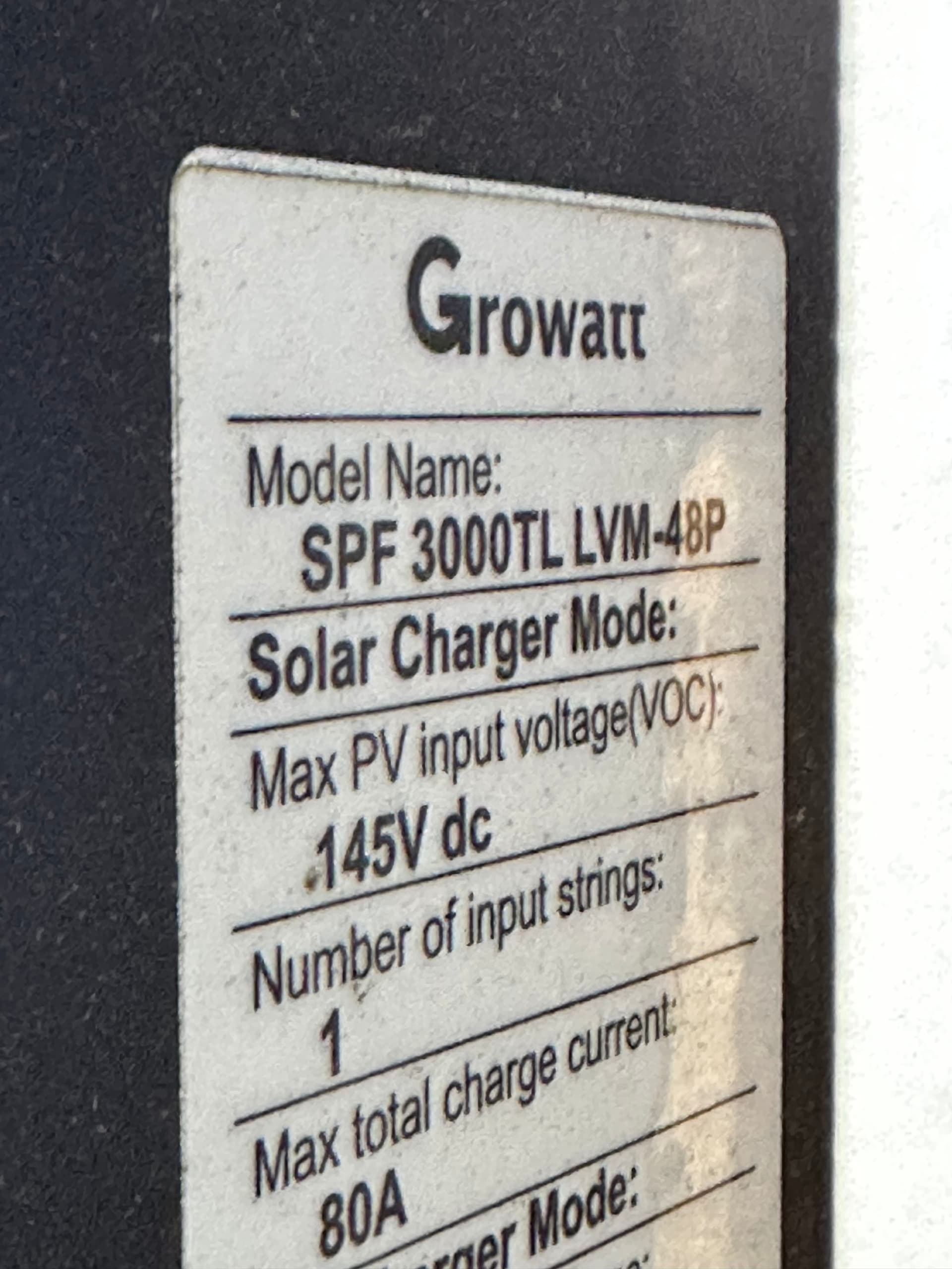
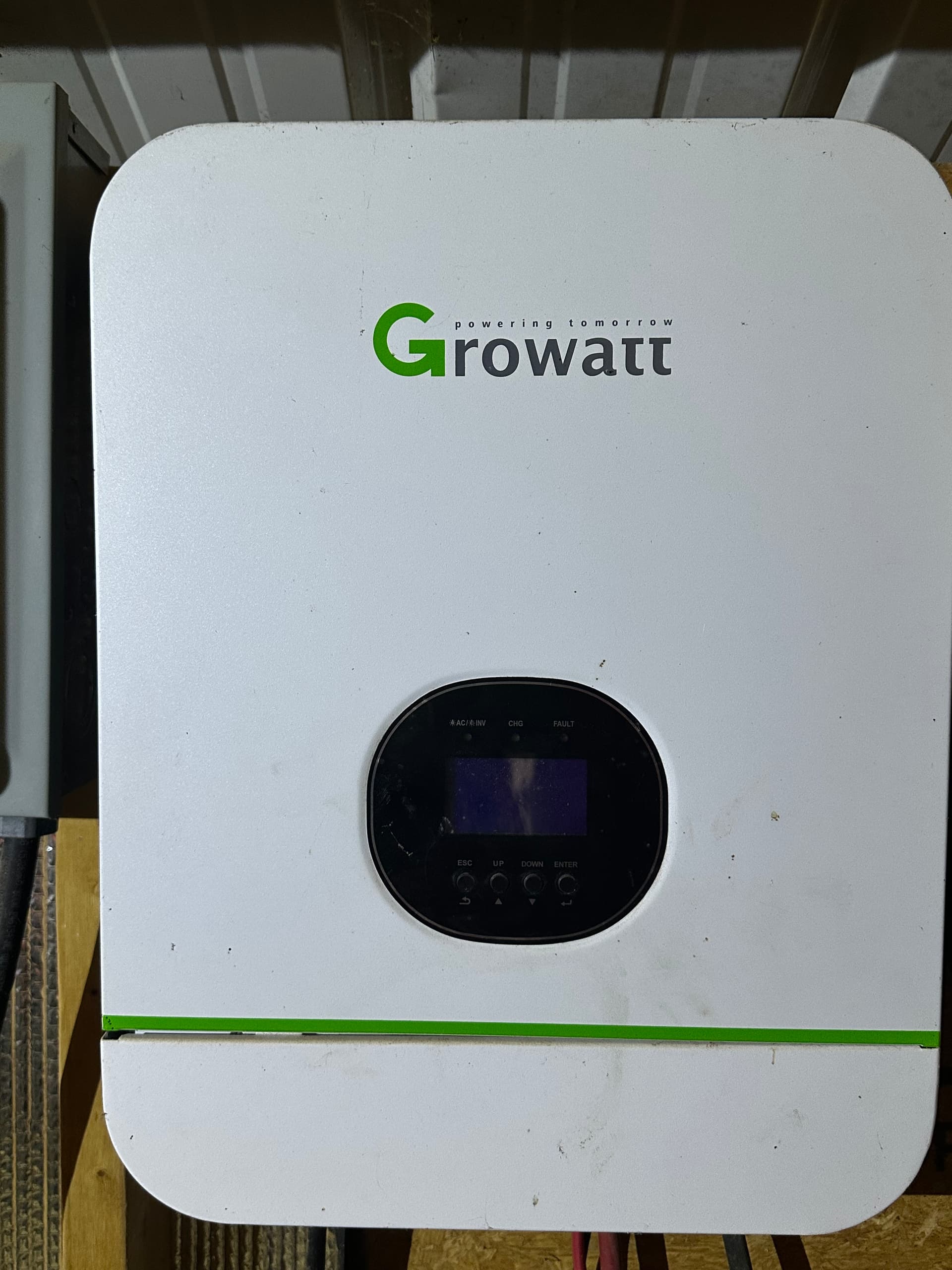
I recently moved to Monterey Tennessee and closer to an old military buddy of mine who lives in Rock Island. He bought a house a few years ago that came with a barn that had a Growatt SPF 3000TL LVM-48P solar setup and 16S LiFePo4 battery bank installed. It is in sad shape, not currently working and he knows absolutely nothing about it. I don’t think the previous owner is with us any longer so I can’t tap into his system knowledge. Best I can do is help my military brother out the best I can. He knows I’m a former Aircraft Electrician, somewhat computer savvy, an MacGuiver of sorts (could be dangerous) and have limited solar experience from owning an 18 panel SunRun Solar system in the past. I live an hour away from this setup so please be patient with my response timing as I may have to make trips back and forth when necessary to continue troubleshooting.
I am in WAY over my head with this setup and I found this community as a result of doing research on some of the existing equipment he has. This doesn’t appear to be a commercial setup but rather a DIY endeavor from the previous owner. The ultimate goal is to try and figure out how to get it running again. I have lots of pictures of his equipment setup and may need additional approvals to get to where I can post them in this forum. For now, a detailed explanation is all I can offer.
The setup in general consists of two individual solar systems. A small 4 panel system and a larger 12 panel solar system.
The smaller four panel solar setup works but has been disconnected for a while. The only reason I’m mentioning this smaller system is it may have something to do with providing a power source for the larger systems Growatt inverter? I need to figure out what the significance of this smaller system is for. There is no other source of electricity in the barn so that might be a missing link to get the larger system operational.
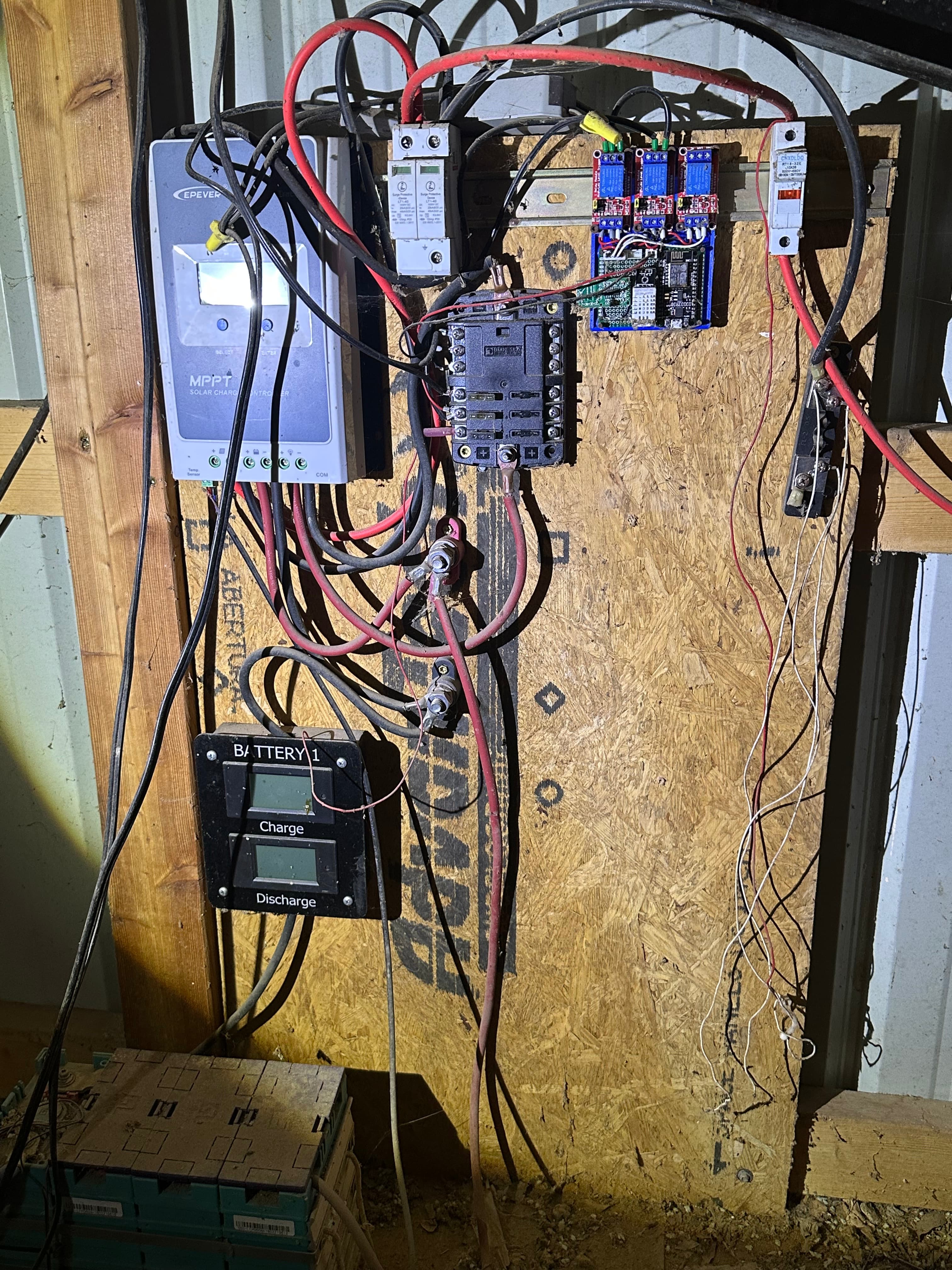
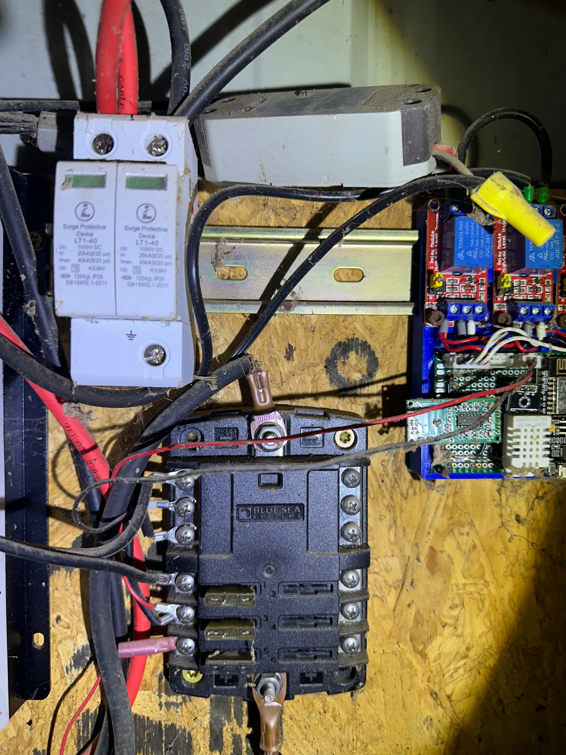
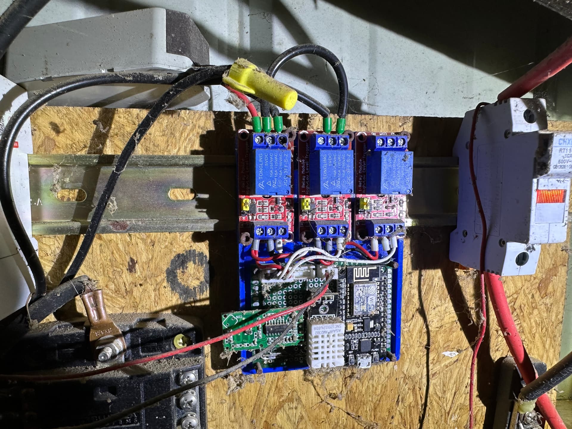
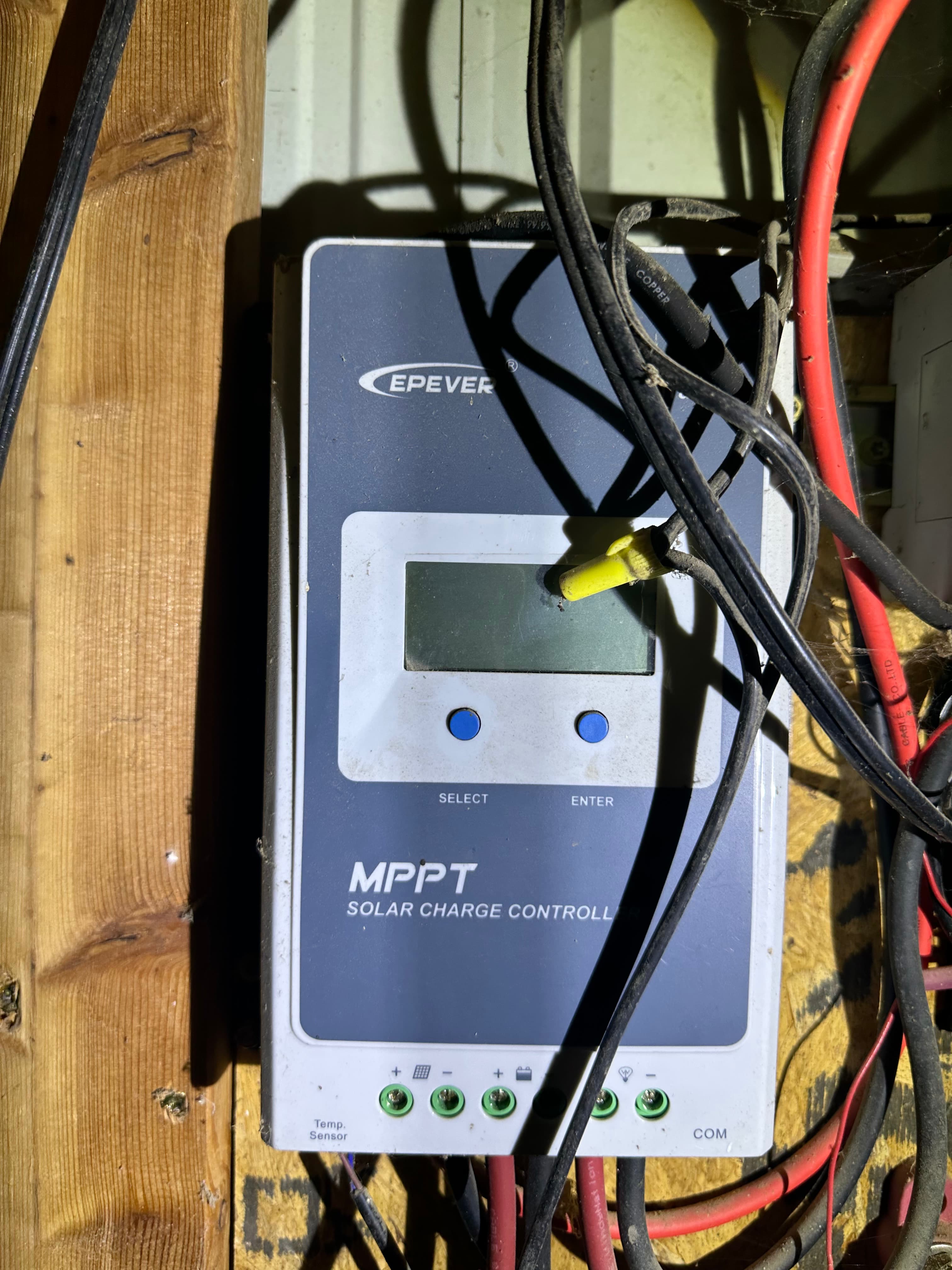
From the four solar panels there is a CHXDLDQ RT18-32X fuse on the red DC+ wire as well as a terminal block looking fuse on the black DC- from the panels. From there the red and black wires go into an LT1-40 Surge protector device, one side for DC+ and the other for DC-. Next in line is an EPEVER MPPT Solar Charge Controller. This provides power to a Blue Sea Systems bus bar looking thing with some automotive type fuses. This in turn provides power to a group of DIY looking PCB boards with three blue relay modules mounted on red PCB boards, one of which is connected to an eMylo RF remote control switch for lights (Perhaps barn lights?). There is also a DIY Wifi board in this PCB group as well. Also from the charge controller, there is a black Battery 1 box with two LCD displays, one for charge and one for discharge. This Battery 1 box is between the controller and four LiFePo4 batteries. The batteries have an Overkill Solar 120A 4S 12V BMS and what looks like DIY PCB Controller with a WiFi port.
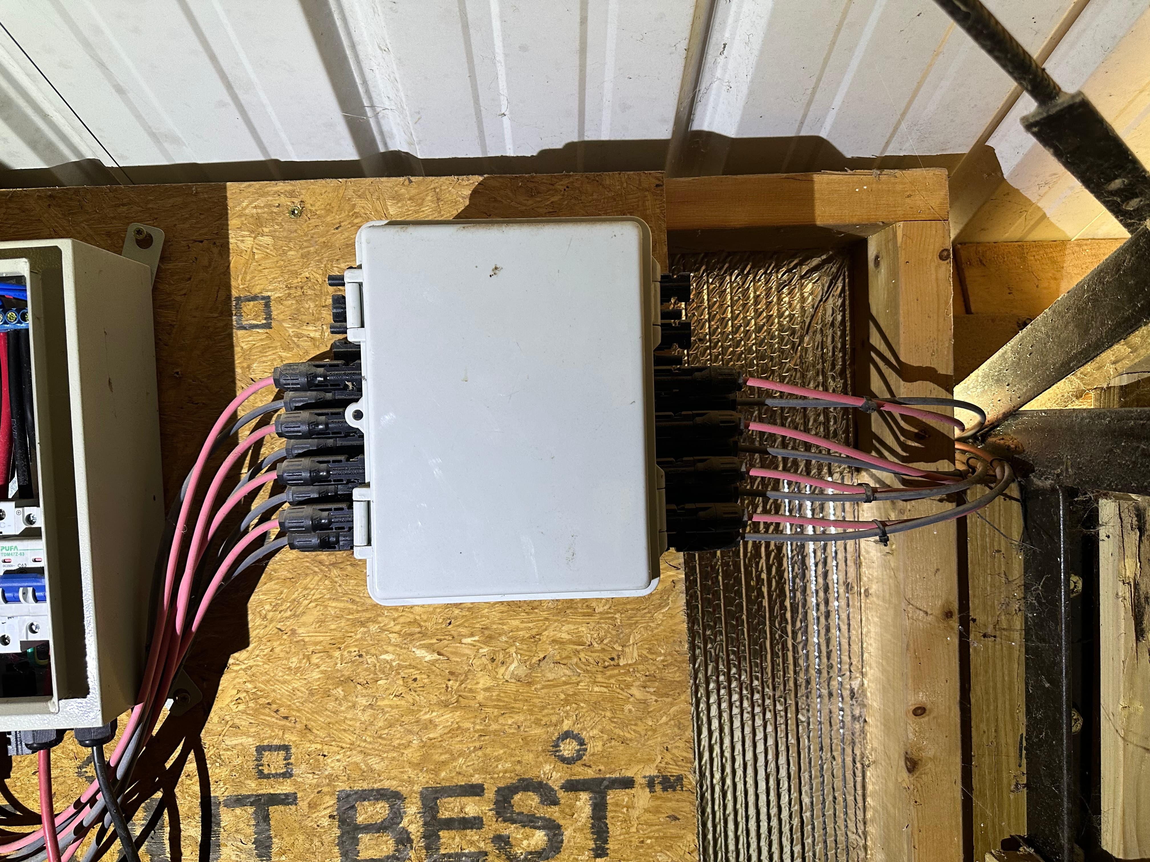
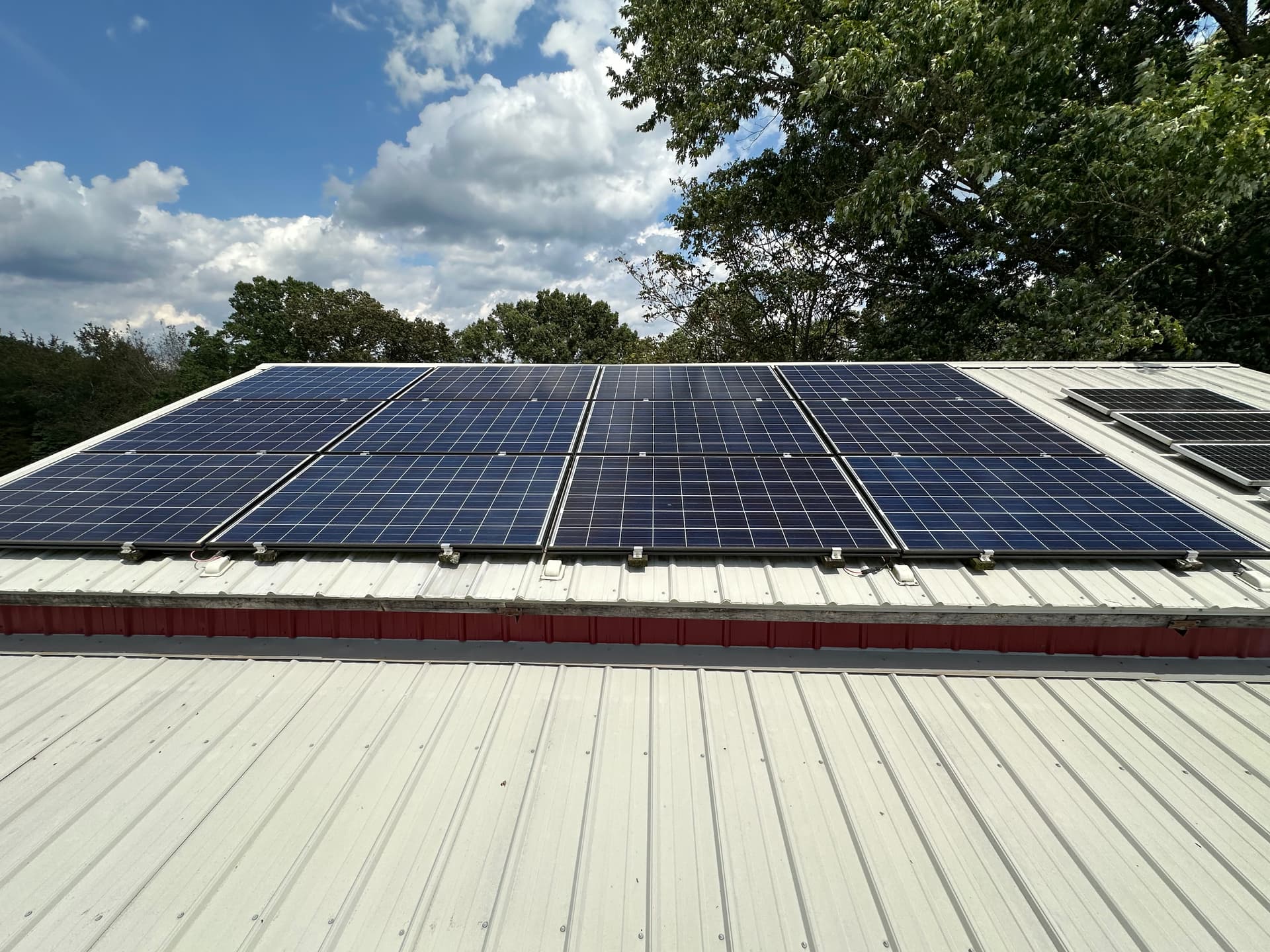
The larger systems consists of 12 large solar panels. I don’t have any idea what the wattage of these panels are or how old they are. The inverters beneath the panels are connected in a way that ties three of the panels inverters together, giving me a single pair of black and red wires from each set of three solar panel inverters. Each of these 4 sets of Red/Black cables lead to a fuse or tie-in box inside the loft of the barn. There are quick disconnects for each wire on either side of the tie-in box.
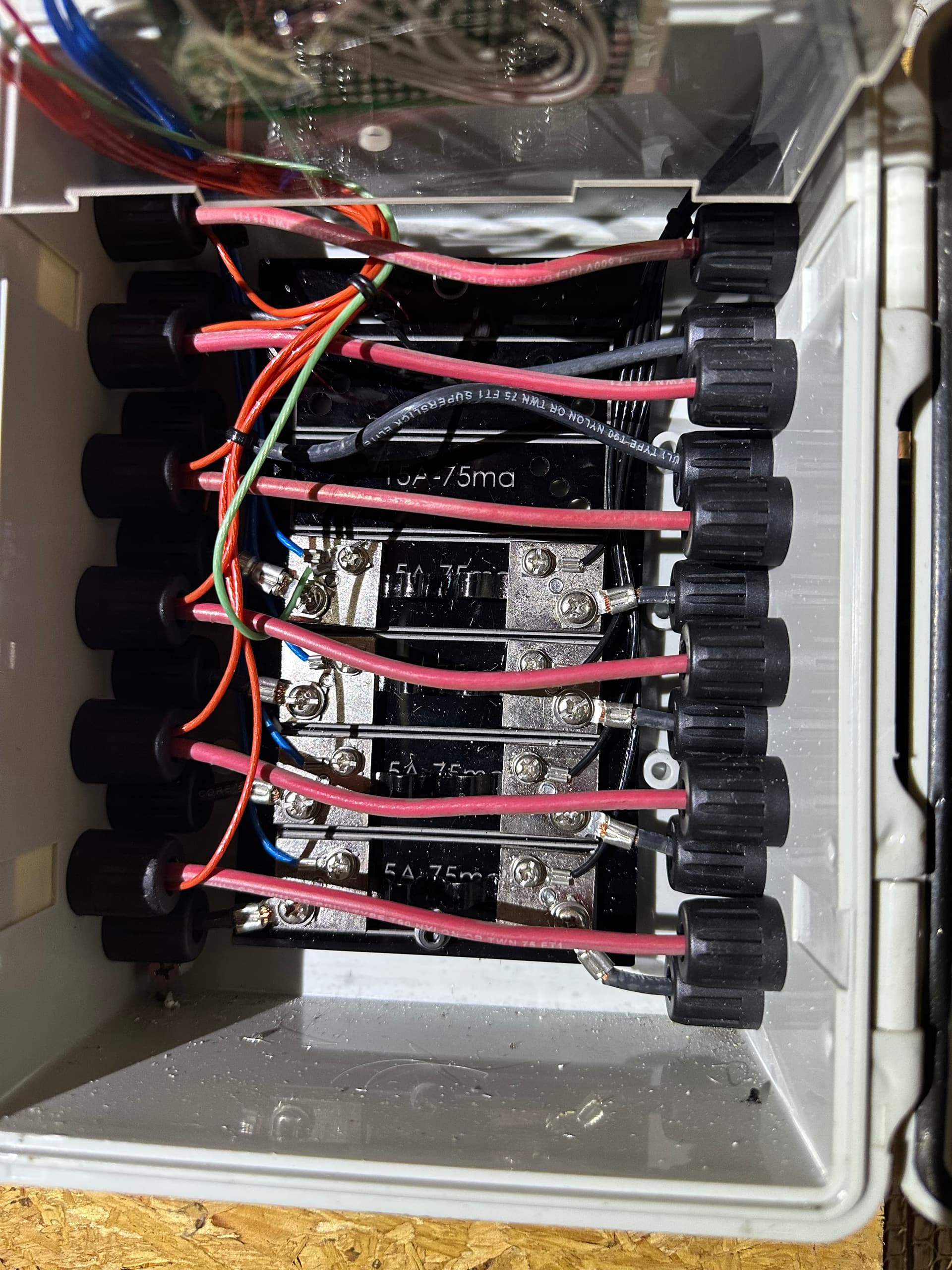
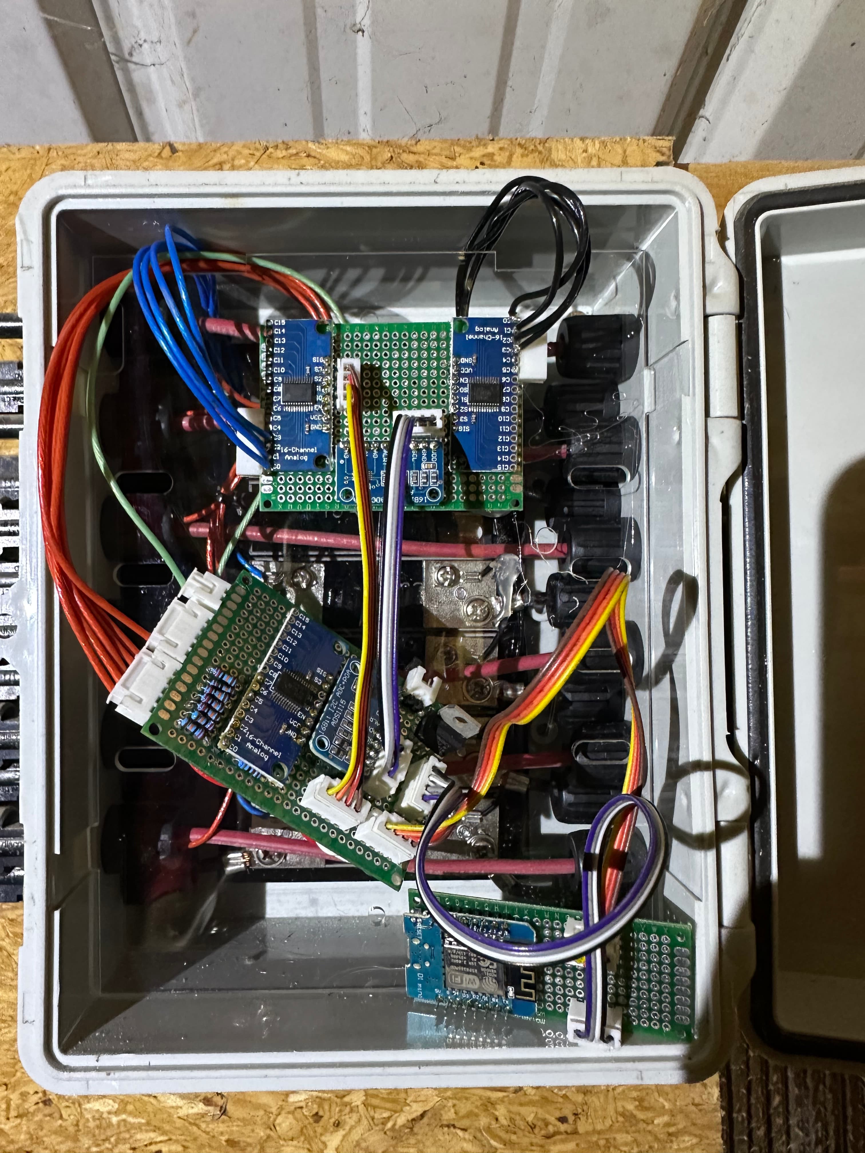
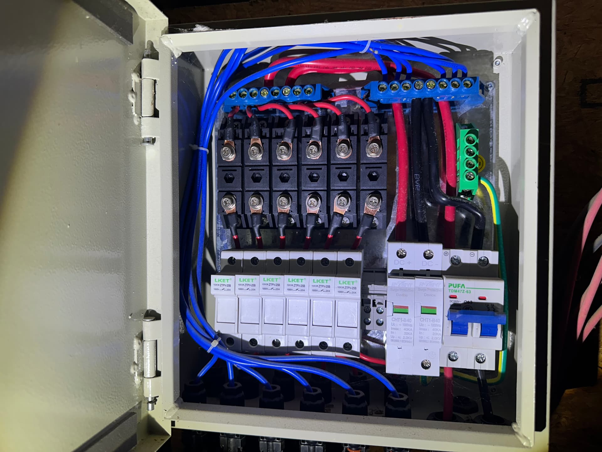
This tie-in box has what looks like 4 inline fuses (5A-75ma written on them) connected to the black wire of each of the 4 sets coming from the solar inverter chains. The red wires appear to pass through. There are 3 PCB boards that look like some sort of panel monitoring interface. The first PCB board has 4 black and 4 blue tap wires from either side of the inline fuses as well as 4 red wires tapping off of the red pass-through wires from the inverters. There are two 16Bit Analog chips, one on either side of the board with a single 16Bit I2C ADC+PGA ACD1115 chip in the middle. This PCB board has two 4 wire patch cables connecting to a second PCB board. One patch cable with yellow-orange-red-brown colors and the other with black-white-grey-purple colors. These patch cables connect to a second PCB board with a single 16Bit Analog chip and a single 16Bit I2C ADC+PGA ACD1115 chip on it. This second board is connected to a third PCB board with a single black-white-grey-purple patch cable. This third smaller PCB board has a patch cable connector (from the second PCB) and a WiFi chip with USB 2.0 Mini-A connector on it.
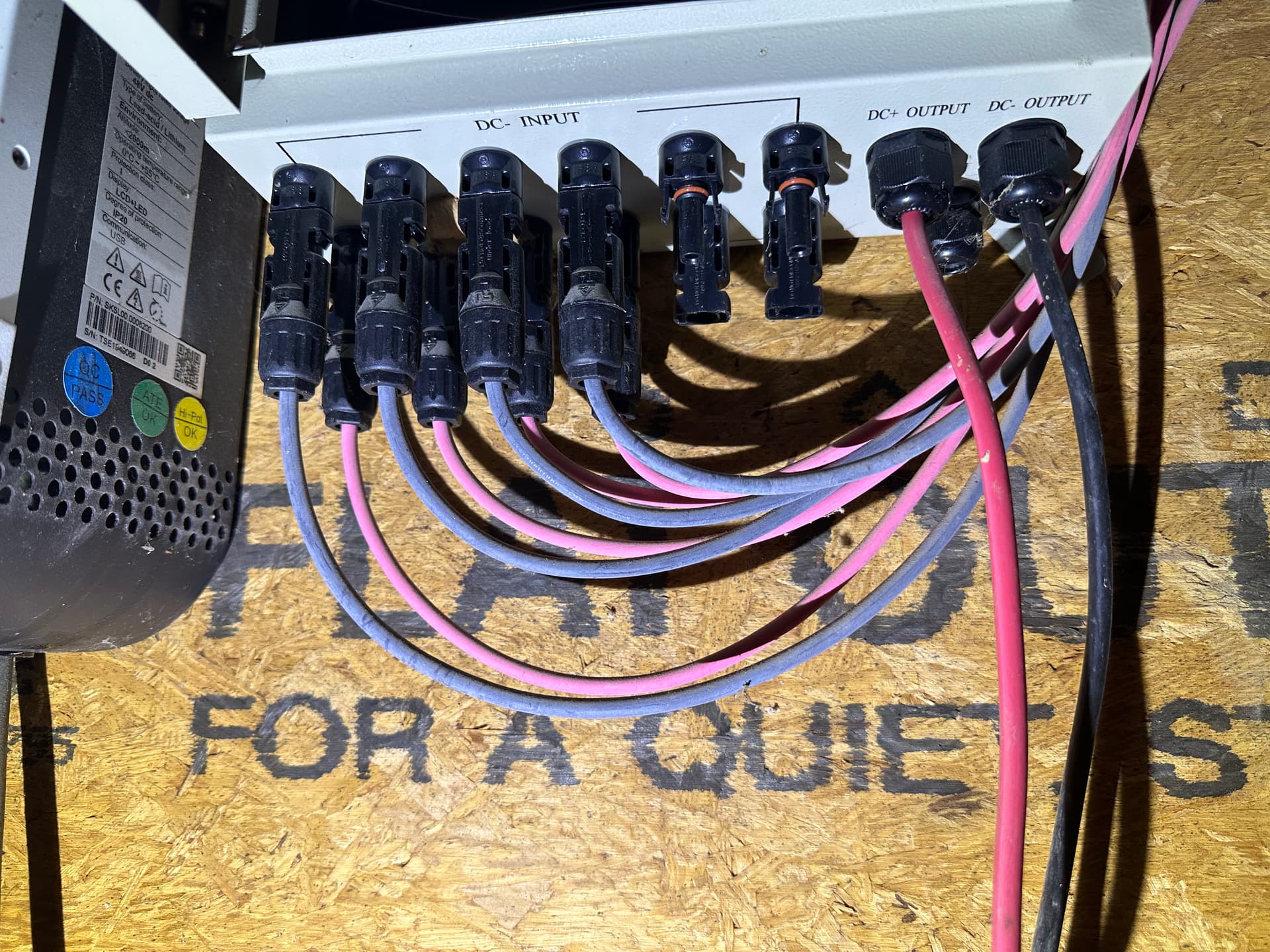
From the tie-in box, these 4 sets of wires go into a fuse block and a bus bar that combines the DC+ and DC- into their respective wires with a surge protector on each wire. There is a DC circuit breaker that breaks the power before it leaves the fuse box and heads towards the Growatt inverter.
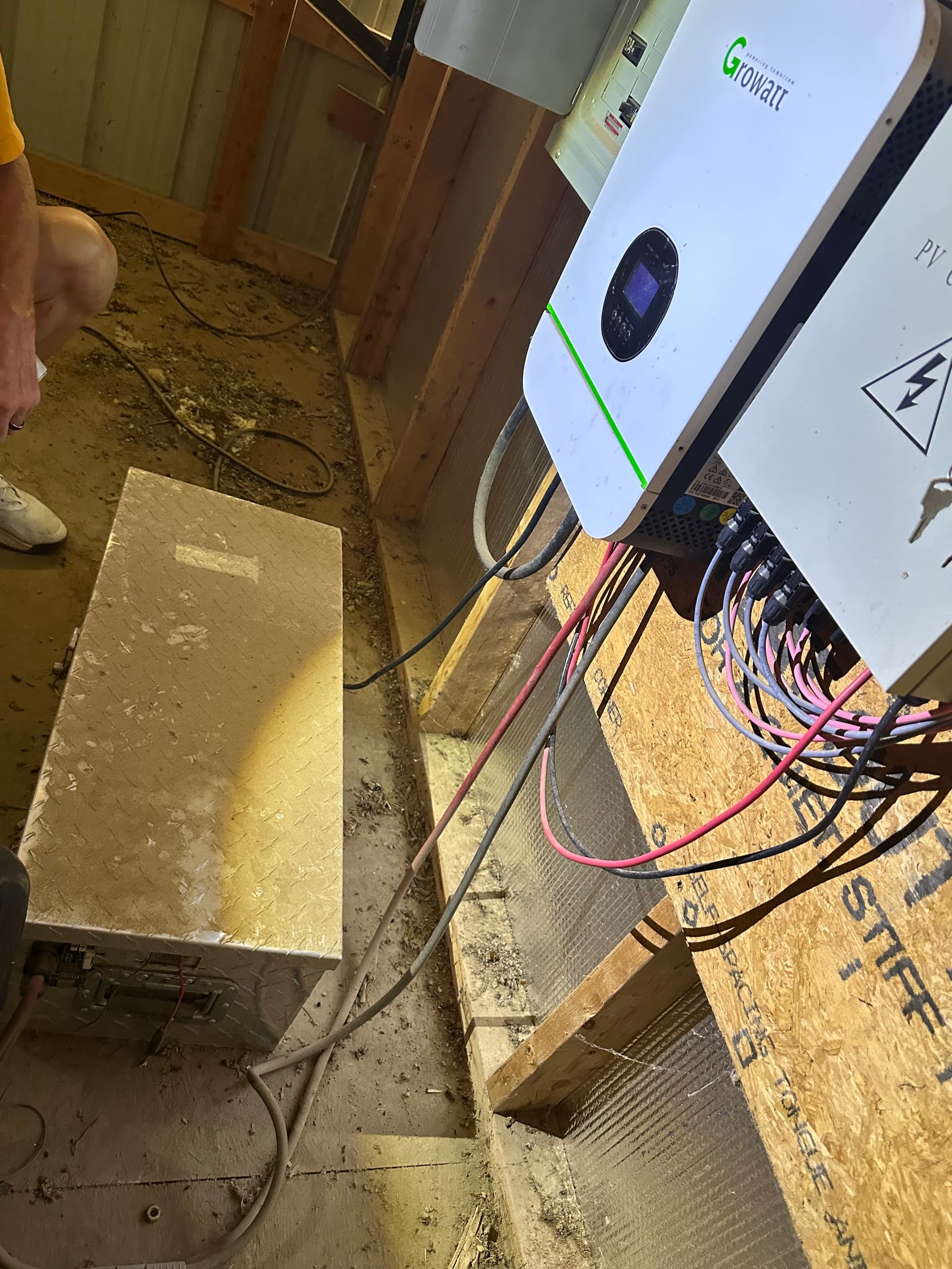
These two DC out wires go into the Growatt inverter via the PV Input. Flipping the circuit breaker in the fuse box doesn’t do anything that I can see. I would have thought that, if the solar panels are producing any sort of power, flipping that fuse box circuit breaker should send power to the Growatt inverter? The inverter isn’t operating at the moment. Perhaps it’s my ignorance but there’s nothing to plug the AC power cable into unless it is supposed to get AC power from the smaller solar setup I mentioned above? Can the Growatt inverter be powered by the DC input from the solar panels or the battery bank alone? The battery box is currently disconnected and removed from the barn for repairs that I explain below.
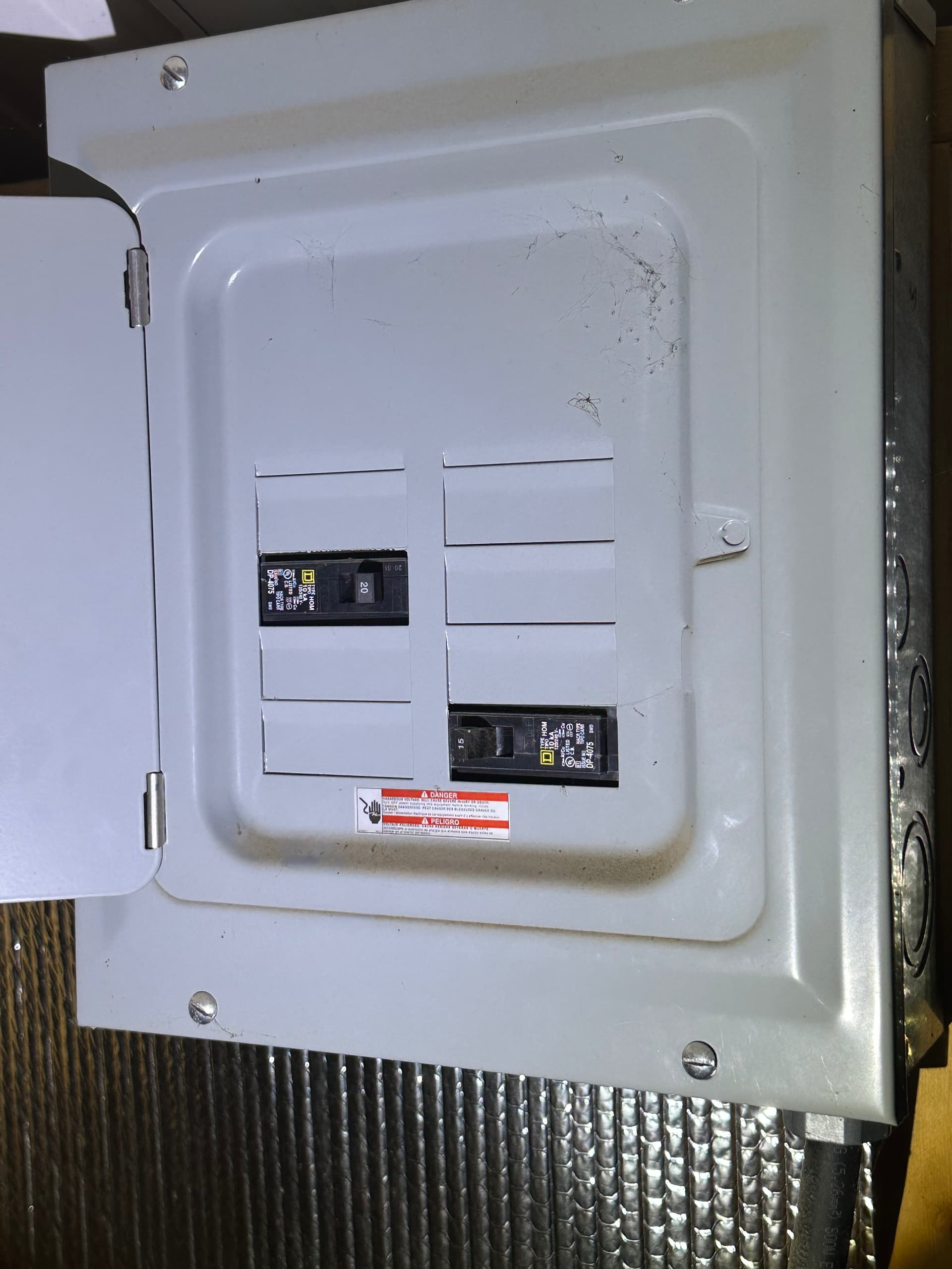
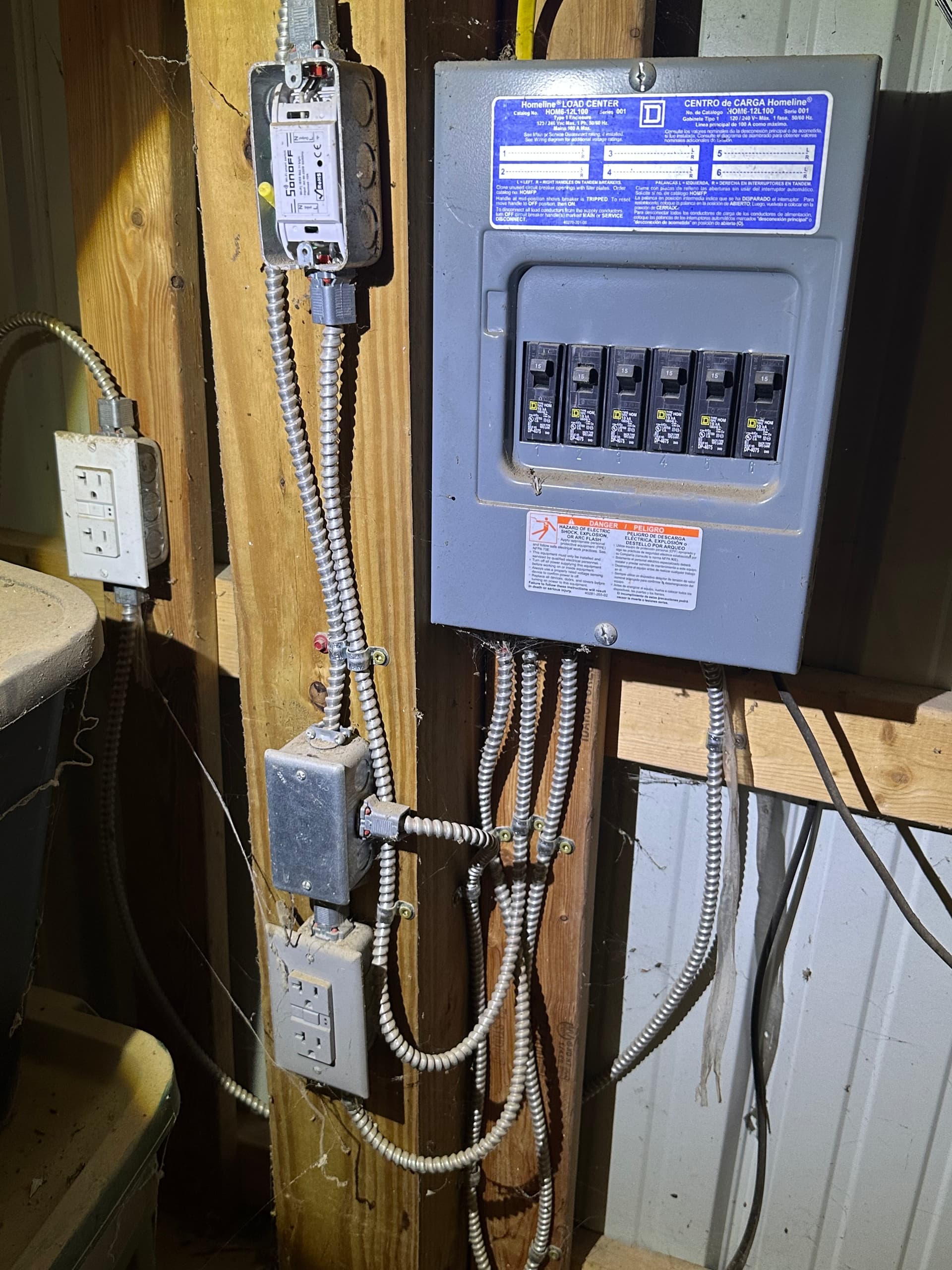
The Inverter has two heavy gauge red and black wire going into the DC input. They come from the battery box which has a disconnect joint (disconnected for safety). The inverter also has a single, heavier gauge black wire (AC Output) that goes to a circuit breaker panel next to the inverter with one 20A circuit breaker and one 15A circuit breaker installed (Both are off). There is also a standard 120V AC plug wire from the bottom of the inverter which isn’t connected to anything. From the circuit breaker panel, there appears to be a single yellow 20A romex cable that goes to a Homeline HOM6-12L100 load center. This box has six 15A circuit breakers that provides power to various outlets in the barn as well as a Sonoff Wifi smart switch of some sort. Not sure what that would be used for but maybe a remote control for barn lights?
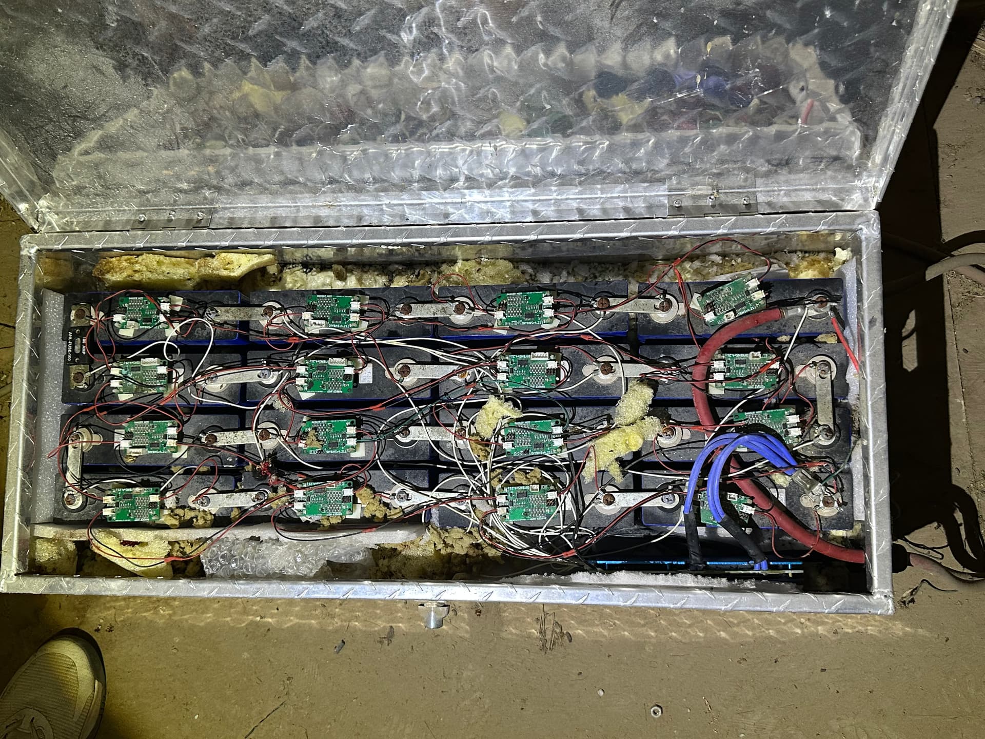
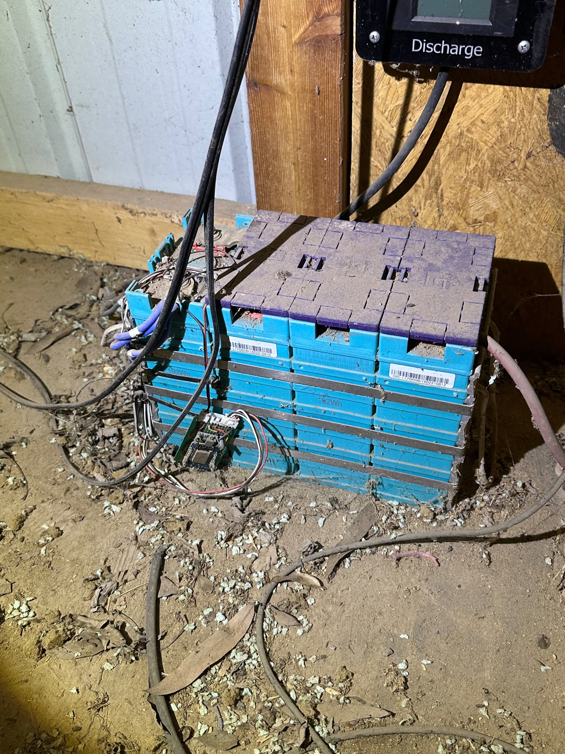
The battery box was my next center of focus and it was in sad shape. I have done some initial repairs to the connectors like fixing the TX1 and RX1 patch cables that seem to connect between the 16 individual DIYBMS V4.21 battery modules. Each module has a two pin TX1, RX1 and Power1 connector. The TX and RX connectors are daisy chained between modules. The Power1 connector has a single two pin connector with red and black wires going to the POS and Neg terminals of the battery the module is attached to. These modules seem to be connected to a DIYBMS V4 Controller with a WiFi chip which I have no idea how to enable or even if it still works.
Some of these module connector wires were damaged by mice eating wire insulation or severing the wire completely. I’ve replaced and/or repaired each connector using my former aviation spark chaser experience while I’m awaiting new connectors to arrive. I tried to logically connect all the TX and RX cables. From the controller, I connected the RX1 to the TX1 of the first battery module that has the positive end of the series chain. from there, I simply connected RX1 to TX1 through each module until I got to the last one on the 16th battery cell. From that module I connected the RX1 to the TX1 of the controller. From what I can tell, there is nothing else connected to the controller board other than the WiFi chip with Mini-A connector.
This battery bank has 16 individual cells connected in series with a PWOD LiFe PO4 16S 48V battery management system. The BMS is connected between the last negative terminal of the series and the external connector that goes to the Growatt Inverter. I checked all of the 16 BMS battery taps as well as the single ground wire. They seem fine, had to repair a few of the tap wires that go to each battery although the existing connection order doesn’t make sense to me yet. There is one white wire going to each of the 16 battery cells however some are connected to the positive terminal and others are connected to the negative terminal. About every three battery cells in this series, there is a single battery that has a white BMS wire on each of the terminals. This is the part that doesn’t make sense to me. I had to repair the single black wire that was connected to the last negative terminal in the series as it was chewed in half.
I put a multimeter between the first pos and last neg terminal of the entire pack and got about 17.5 volts. That’s a little more than a volt per battery. They haven’t been charged in a while but my friend says the previous owner, who I think is no longer with us or at the very least no longer reachable, came out to look at the setup about a year ago and my friend remembers seeing LED light activity in the battery box (Modules balancing perhaps). When I put the multimeter between the pos and neg wires at the battery side of the connector break that is between the battery and the inverter, I get .5 volts. This test has the BMS in the loop with leads me to believe that either the BMS is shot, something isn’t connected properly or there’s not enough voltage in the packs to allow for a proper BMS operation. Perhaps there’s a min voltage required to allow the BMS to do anything? All I know is with all the RX and TX cables daisy chained between the modules and connected to the controller, there is no activity on the modules in the form of LED lights or apparent balancing action.
I have a single ~12 gauge red wire with an automotive type fuse block (no fuse) that leaves the battery box and connects to nothing. It appears to have been chewed or mangled and there’s nothing in the immediate area that would suggest it went to anything close. There is a singe 18 gauge green wire coming from the last negative terminal of the pack series that was severely chewed and also goes nowhere that I can figure out (Possibly a ground wire of sorts). Lastly there is a single black wire, same size as the BMS wires (~20 Guage), connected to the last neg terminal of the pack which leaves the battery box and was just hanging. It appeared to be cut and I have no idea where it goes or what it might connect to. There were no dead rats so I don’t think any of them electrocuted themselves but I can’t rule out some of the module connectors shorting out due to them chewing the connector wires. Some were chewed clean off, right up to the two pin connector. Nothing looks burnt out on any of the controllers but some have minor corrosion from exposure to moist air (or rat piss).
A few remaining comments about this setup. I found a Growatt Wireless module lying around nearby. Not sure how to use it or where it needs to be connected but the connector on it looks like it would connect to the USB Mini-A port on the WiFi chip on the battery controller board and the same type of WiFi board in the tie in box mentioned above. I’ve been surfing the forums since I joined trying to self educate and found an image a similar WiFi controller module with a USB Mini-A cable connected. I can’t tell what it was connected to but no doubt to some sort of visual interface?
I don’t have, nor do I know anything about Raspberry PI setups but I’m thinking I might need something like that to interface with this type of system. That would be a whole different rabbit hole to go down. I have an iPad and a Mac Pro Laptop available but I’m not sure if there is an app or software program that I need to perhaps interface with any portion of this solar setup.
Any ideas, suggestions would be super helpful. I think my first task is to get AC input to the Growatt inverter followed by making the battery safe. I’ll figure out how the WiFi monitoring plays into the overall setup. I can send additional pictures and explain further in detail about various portions of this system if something I’ve written doesn’t make sense.
Thanks in advance!
Cheers!
Rick