My solar pv system is a capacitor?

I installed emontx’s and emoncms in my house a few years ago. My emon base eventually crashed and recently I’ve resurrected it, but since it was last running, I have a new 35 panel solar system installed in my house.

The main cable from my circuit breaker box to the utility meter is thicker than the emon std CT’s can encircle, so I’ve not been able to monitor those in emonCMS. But I do have another monitoring system, efergy, that has been monitoring that line and claiming higher usage than what I would expect based on adding up my emon monitored circuits and assuming after some spot testing that the other (minor) circuits are not consuming any watts. This became a mystery for me to look in to.

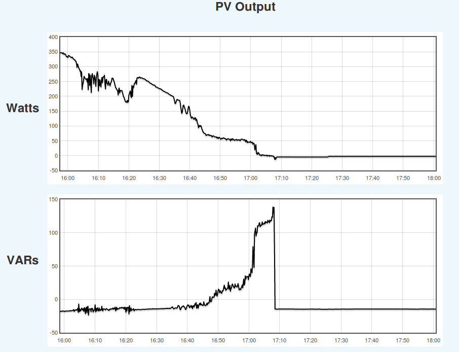
To reduce the number of unknowns/variables here, because I don’t have enough CT’s to monitor all circuits, I’ve started debugging by turning off the circuit panel’s master switch. As a result, the utility meter should be connected only to the solar system. To reduce the variables even further, I do this at night when the panels should not be generating any energy. I expect the wattage on the solar panel line pair to be zero and emontx shows those lines with almost no watts. (It shows 30 watts which I assume is basically zero.) OTOH… the efergy shows 500 “watts” on the utility line. Because the only thing connected to that utility line is now the solar system that’s showing (almost) no watts, I’d expect the efergy to show zero, not 500 watts.

I’ve since purchased a clamp amp meter to help me check if the efergy is nuts. Unfortunately the circuit panel is very crowded so I can only sample a few lines. Nevertheless, limited evidence suggests that the efergy is correct that there is about 2.1 + 2.1 amps on the solar panel line at the same time that the emontx’s are reporting about 30 watts. (efergy does not monitor voltage at all and just assumes 120vAC (and power factor 1.0?) and calculates “watts” [sic] based on that.)

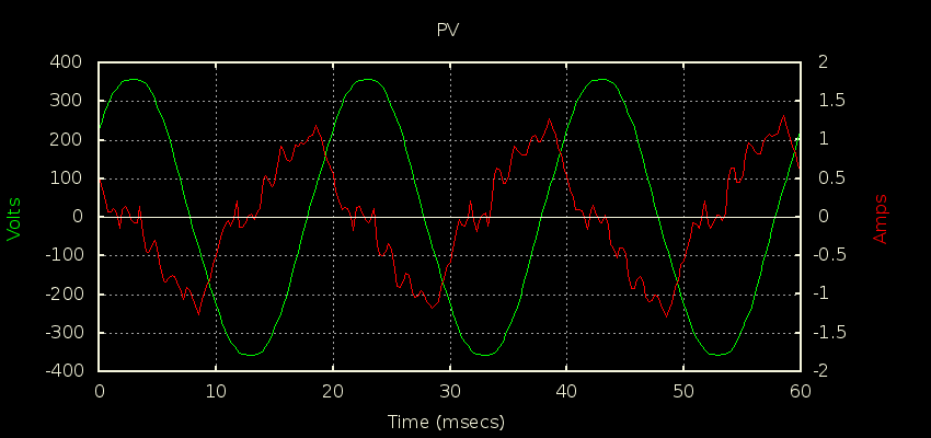
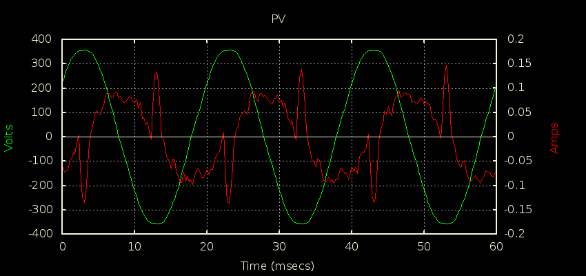
The only explanation I’ve been able to come up with is that solar panel system is acting like a capacitor which must be resulting in a power factor of around zero so the emontx shows almost zero watts while there appears to be 4+ A of current.

Does this make sense? Would you expect a solar system to act like an capacitor (or inductor)?

Is there a fairly easy way I can modify a emonTx to reveal the power factor or take a synced snapshot of the current and voltage waveform?

J.

Definitely possible, and I think others have reported very lousy power factors from their inverters at night especially if you have a bunch of micro inverters.

Mine is slightly capacitive during the day while generating, and also at night once it moves to “goodnight mode”, but there is a small window of about 5 minutes at dusk between when it stops outputting power but hasn’t gone into goodnight mode yet. During that window, it appears as a big inductor (~148 VAR). My guess is it has some big honking transformer in it that it probably isolates in goodnight mode. Maybe yours doesn’t and just leaves it connected all night.


In this pic the CT is facing away from the inverter, so +ve power means the inverter is producing, but I’ve flipped the sign of the VARs to make it look like the CT is facing the inverter in the second graph so +ve VARs means the inverter is looking like an inductor.

Yes, I think there is since it calculates Irms and Vrms it’s pretty easy, but I think it involves sending the extra information in the RF packets, and tweaking the receiving side to expect the extra field. Others here are way more qualified than I am to talk you through what’s needed.

No, it doesn’t have the bandwidth and/or RAM needed to do that, mine does though. The first pic below is how it looks during the 5 minute window, and the second one after it’s gone into goodnight mode. In both cases you need to mentally flip the Red (current) trace because of the way the CT is facing. The first plot is pretty much pure inductor and the second looks more like a classic switchmode power supply signature. Also note the different y-scales: much smaller currents once it goes into goodnight mode.


1 Like

Nay, probable. An inverter can, very roughly speaking, take a slice of current anywhere it likes on the voltage wave, so yes, it’s almost certain to appear reactive.

That I doubt. Those are expensive and heavy - what you’re seeing is much more likely due to the electronics taking current that looks inductive due to the phase angle. (Unless, as I suspect some do, it’s trying to clean up distortion on the mains and injecting current at a point on the wave that has that same effect.)

That’s exactly correct. You don’t even have to do the sum, ct1[or whatever].powerFactor is already available to you, multiply it by 1000 (to make it an integer) and add it to the PayloadTX struct “emontx”, and in emonHub (if you’re using that), add it to the Node parameters with a scale factor of 0.001 (to turn it back into a decimal with 3 digits precision).
But emonLib calculates the power factor from the definition, so it won’t give you the sign - leading or lagging. To do that, you’d need to do something like the 3-phase sketch does and delay the voltage wave, but by 90°.

Look at the “Use in North America” page. There are plenty of larger CT’s listed there. The YHDC one doesn’t even need you to change the burden resistor.

I suspect that’s 30 W consumption to keep it alive overnight.

Shame on you :open_mouth: :grin:

As far as I know, that’s correct. Very many “energy” monitors only measure current, and guess voltage, power factor, or both, and call the result “Watts” - most likely because it’s all but impossible with a battery-powered transmitter and CT to do otherwise, and in any case most of the time it’s good enough for the average technically illiterate consumer to whom VA and power factor, and even the difference between power and energy, is meaningless.

Yes there is, but not at the same resolution as dBC’s. Robin Emley has produced sketches that do just that, all listed at Robin's Mk2 Code variants and associated tools. | Archived Forum
I think you want “RawSamplesTool_4ss_2”

I suspect it’s quite a bit lower than 30W. The 2.1A is small by emonTx standards, small enough that the CT is probably operating in the large phase error zone. But 2.1A is also large enough that it won’t take much phase error to incorrectly show up as 30W.

With a little (?) noise pickup thrown in, no doubt.