Why are you using the same input pin for both voltage and current? That is impossible. You must have the correct pin numbers.
Here are the method definitions: void EnergyMonitor::voltage(unsigned int _inPinV, double _VCAL, double _PHASECAL); void EnergyMonitor::current(unsigned int _inPinI, double _ICAL)
inPinV is the input pin for the voltage signal,
inPinI is the input pin for the current signal.
What you have done is, you are measuring the emon1 current using whatever is on A0, and the emon2 current using whatever is on A1.
You are measuring the emon1 voltage using whatever is on A0, and the emon2 voltage using whatever is on A1.
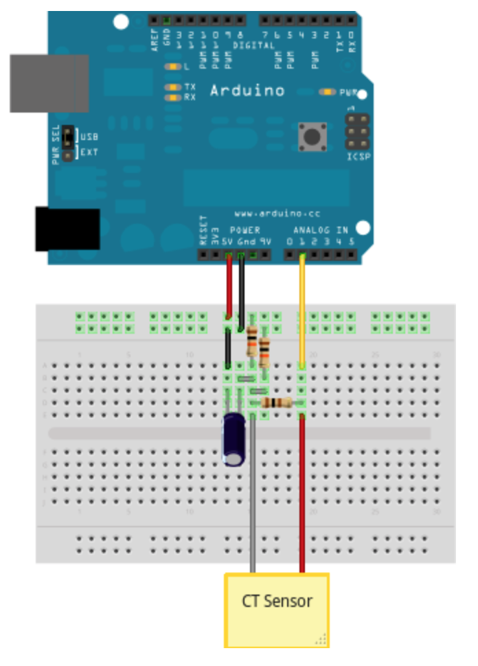
I was remove emon.voltage and monitor measuring current only following pic above and duplicate CT sensor to 2
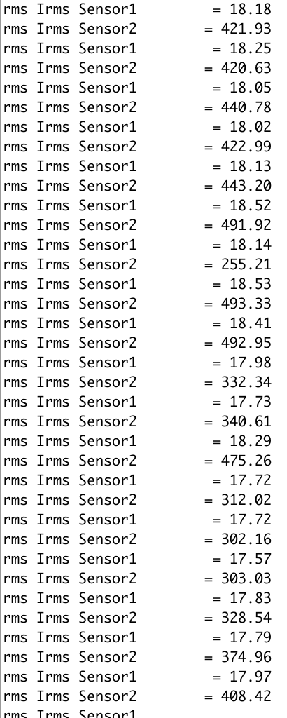
I still got a problem emon1 is correct 17.xx but emon2 value is 6.xx why it’s so different
Yes i do working with the same as your suggestion code
void setup()
{
Serial.begin(9600); //emon1.voltage(A0, 221.5, 1.7) ; // input pin, voltage calibration, phase calibration
emon1.current(A0, 220); //emon2.voltage(A1, 221.5, 1.7) ; // the same numbers as emon1
emon2.current(A1, 220);
}
void loop()
{
delay(500);
double Irms1 = emon1.calcIrms(1480); // Calculate Irms only
double Irms2 = emon2.calcIrms(1480); // Calculate Irms only
Serial.print("CT 1: “);
Serial.print(Irms1*230.0); // Apparent power
Serial.print(” ");
Serial.println(Irms1); // Irms
Serial.print("CT 2: “);
Serial.print(Irms2*230.0); // Apparent power
Serial.print(” ");
Serial.println(Irms2); // Irms //emon1.calcVI(20,1000); // 10 cycles (20 zero crossings) timeout after 2000 m
But i still got value from between sensor1 and sensor2 so different as the same power source
Sensor1 is correct 17.xx but Sensor2 value is 6.xx is not correct
I’m not sure about the circuit diagram what should i connected when i need more than one CT Sensor, I’ll go back to check for make sure the circuit is correct connected or not