Hello together, may someone can answere the question, is it pissible to connect more Controllerboards to one CanBus and what will then be shown on Victron side?
Don’t know if anybody has tried but all indications are that it cannot work. See this link Can I connect more than one BMS to the Venus GX? - Victron Community
The controllers would need to talk to each other and elect one as the ‘master’ to communicate directly with Victron on behalf of all others. This is how Pylontech and likely Victron batteries accomplish it.
maybe it can be possible in future if stuart integrate this in the firmware
A GITHUB issue has been opened for this…
Thanks very much for the hint, may it would be an better option to do it as the Pylontech do it. Use CAN as the connection for the Main Controller and connect the following by RS485 (as it is already on the board). Also probably it is not requested to connect several Shunt-modules, they could be easy addressable on Unit IDs.
It would be really great if you could think about such a solution, as i would say, this is the last feature which is missing to compete with the big BMS supplyers.
Never the less, you did a really great Job with the last huge update @stuart . Thanks very much.
/ Chris
The key point with this Chris, is that a single controller can handle up to 128 cells, so multiple cells in parallel can emulate a bank of pylontech batteries for example.
So there isn’t really a need for multiple controllers, unless you have a requirement for fail over or high availability.
Using 280ah cells for example, you could have 8x16 cells in parallel, for over 110kwh of storage, still with a single controller!
but how slow will the response time be, 5-6 seconds? not realy practical
Why do you need it quicker? What benefits does that bring?
well other bms are quick, response time under a second
but im doing well with 32 moduls and a roundtrip of 1,5sec
i am runnig offgrid a electric heater for my hot water
if the temperature is reached it switches off and the 4kw are going into battery then the voltage rise insanely quick.
you can imagine full battery with 56v then suddenly apply 4kw to it.
my sma sunny island need time to increase the hz for sunny boy to ramp down and as faster the bms tells them what to do, the better.
with 1,5seconds my voltage rises to 57,5v. i can just imagine what happens with 6sec response time.
but this is just for my case, for others the actual speed is fine i think.
This is where the CAN integration with the charger and the DIYBMS current shunt comes into play - the individual modules as just there to monitor single cell voltages and provide balance function.
The current shunt looks after the pack voltages and current sensing, proving useful data to the charger to limit its charging voltage/current.
In your example, a 56V battery would have its charging parameters limited by CANBUS, so it won’t dump 4kW into them.
Am likely too late to this discussion but wondering if anyone here has any insight regarding the related github issue #184 in terms of progress?
From the issue comments it seems some degree of coding/testing was done but there doesn’t seem to have been any related (public) fork of or contribution to diyBMSv4ESP32 code - not sure why.
There was a recent issue comment about “one more person testing on Victron but we need all the help we can get” and at least two respondents (including myself) but nothing heard since…
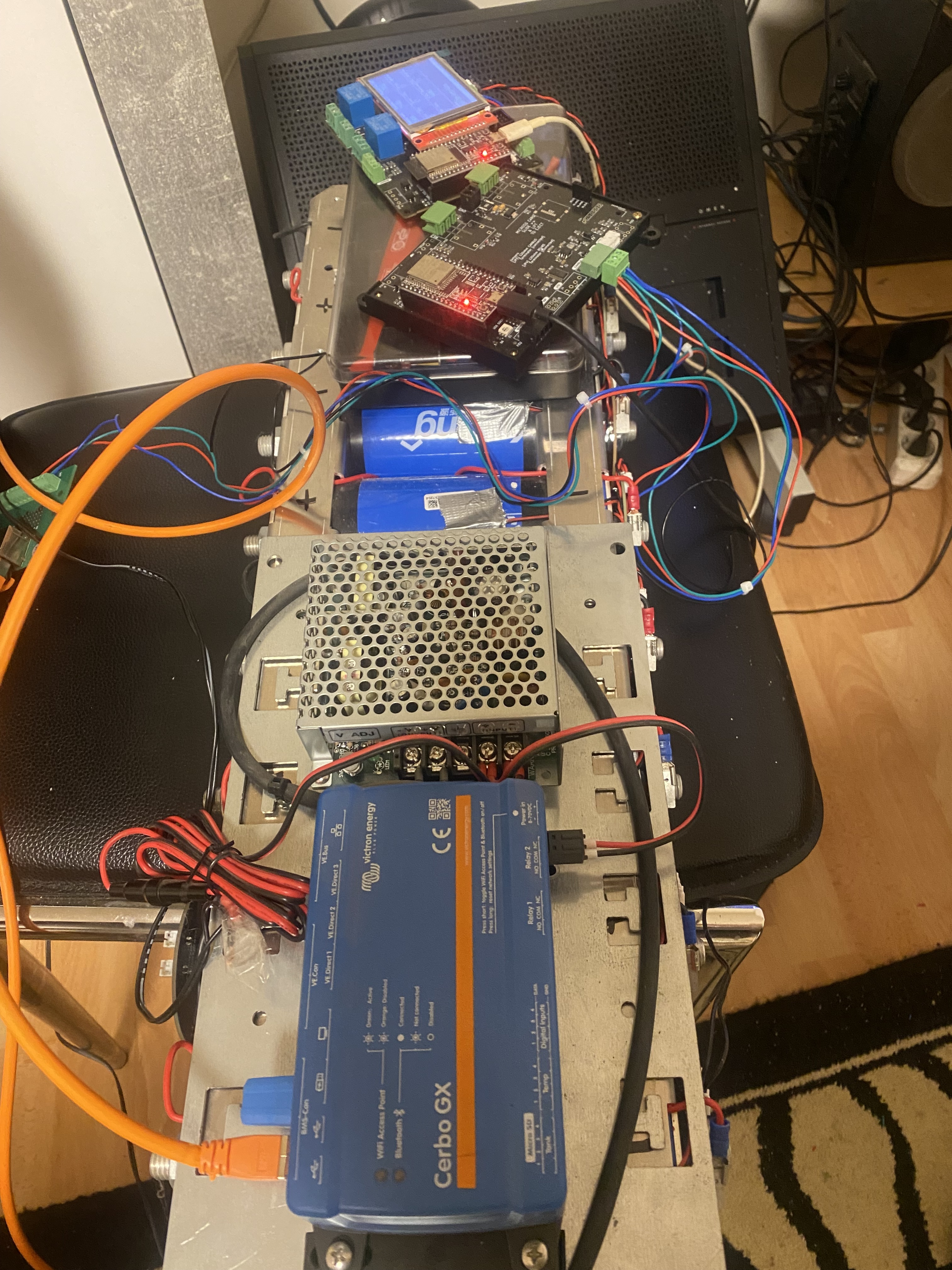
I’m working on building a modular ‘battery’ consisting of multiple (16S1P) packs, each with it’s own controller/shunt/switching etc but connected in parallel and therefore presenting as a single pack.
@stuart - my aim is to set up something like two or more of your powerBasket ‘packs’ to work together where all cells are individually monitored but where each pack can be managed independently, each with it’s own protection mechanisms etc.
Now I do understand what you meant by:
a single controller can handle up to 128 cells, so multiple cells in parallel can emulate a bank of pylontech batteries for example
…but it’s just not quite as modular in terms of easily being able to add/remove a single pack for whatever reason.
Judging from other discussions, I suspect there is some interest in having a modular pylontech-like capability but I guess it depends on how this project evolves though I’d like to contribute where I can.
-p
I have been testing this version of firmware for 4 months now. works like a charm.
I was one of those volunteers and have a test system up and running. I do not have a copy of the source to share: I was only a tester. I think it would be smart to update Stuart on the progress because he asked to be kept in the loop. I do not know if that has been done.
In other news, I found this today and thought it was an interesting approach to parallelize packs. It doesn’t address our specific use case, but interesting nonetheless. GitHub - limpkin/xt60_parallelizer: a custom board to monitor custom battery packs
Tim
Here are the new functions described in detail:
initializeBMSIDs() Purpose: Assigns unique IDs to all BMS modules during system initialization. It ensures that each module has a valid and distinct ID.
Functionality:
Iterates through all modules (default: 10 modules). Checks the stored ID in the EEPROM for each module. If an ID is missing (set to 0) or invalid (greater than 100), a new ID is assigned. Newly assigned IDs are incremented sequentially starting from 1 (lastID). Updates the EEPROM with the new IDs and ensures the changes are committed. Example Behavior:
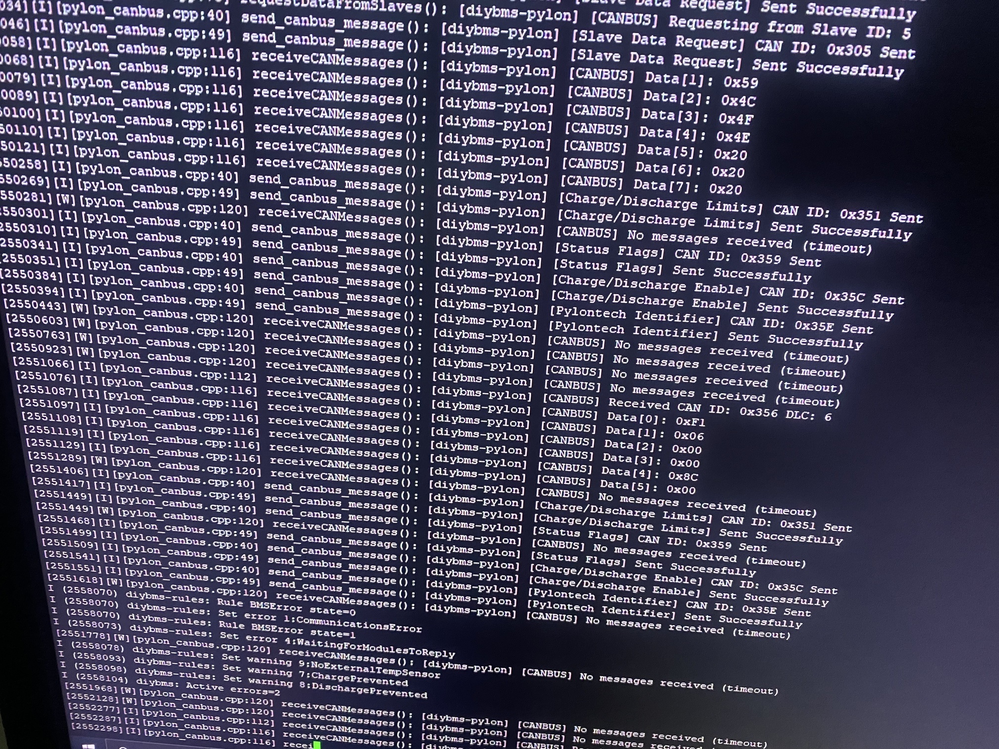
Module 1 has no ID stored (value = 0). Assigns ID 1. Module 2 has ID 55. Keeps it as-is. Module 3 has an invalid ID (255). Assigns ID 2. 2. assignMaster() Purpose: Identifies and assigns the master BMS module based on the lowest module ID.
Functionality:
Reads all stored IDs from the EEPROM. Determines the module with the smallest ID. Logs the ID of the master module. Use Case:
The master module acts as the coordinator and manages communication with other BMS modules and external systems like the Victron Cerbo GX. 3. checkDuplicateIDs() Purpose: Detects and resolves duplicate IDs among BMS modules to ensure unique identification.
Functionality:
Compares the stored IDs of all modules. If a duplicate ID is detected: Assigns a new unique ID to the conflicting module using lastID. Updates the EEPROM with the new ID and commits the changes. Logs a warning whenever a duplicate ID is corrected. Example Behavior:
Module 1 and Module 3 both have ID 5. Module 3 is reassigned a new ID, e.g., 11. 4. setupCANCommunication() Purpose: Initializes the CAN communication system for data exchange between BMS modules and the master module.
Functionality:
Configures the CAN driver with default settings: GPIO pins for CAN RX and TX. Bit rate set to 125 Kbps. Accepts all incoming messages (no filters applied). Starts the CAN driver. Use Case:
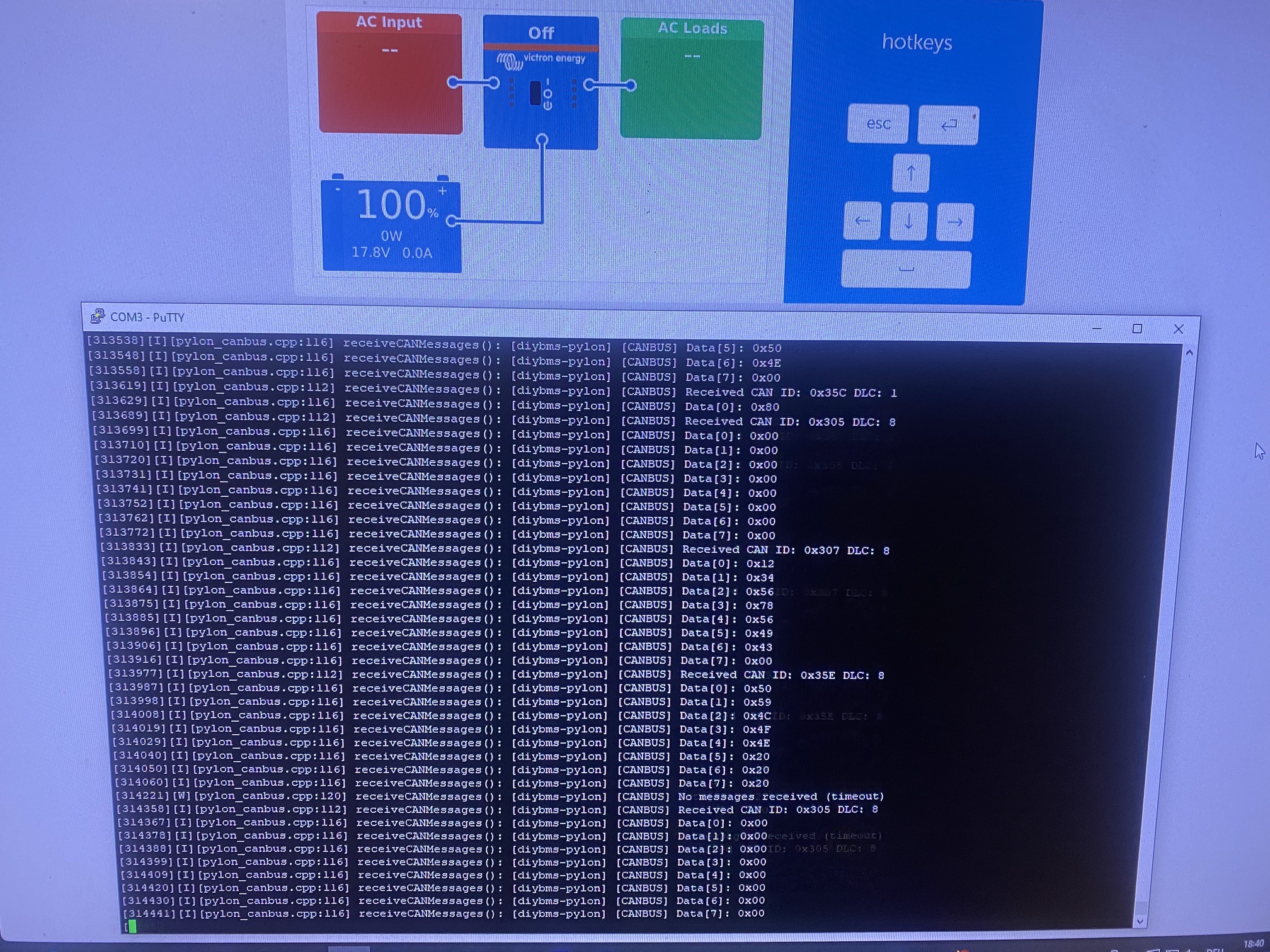
Sets up the CAN bus to facilitate communication between BMS modules and external systems like Victron Cerbo GX. 5. processIncomingCANMessages() Purpose: Processes incoming CAN messages received by the system.
Functionality:
Listens for messages on the CAN bus. Logs the details of each received message: Message ID. Data length. Can be expanded to handle specific message types or respond to requests. Example Behavior:
Receives a message with ID 0x100 and length 8. Logs the information. Summary of the New Features Automatic ID Assignment:
Ensures all modules have unique and valid IDs. Master-Slave Architecture:
Assigns a master module based on the smallest ID. Duplicate ID Resolution:
Detects and resolves conflicting IDs automatically. CAN Communication Setup:
Configures the CAN bus for seamless communication between modules. CAN Message Processing:
Handles incoming CAN messages, enabling integration with external systems like Victron devices. These features collectively enhance the robustness and functionality of the BMS system, ensuring reliable operation and efficient communication in a multi-module environment.
1 Like
Hello Goran, what you have done looks very interesting. I will try to test it, I am still missing controller boards.
Have you already tested it in productive mode?
For the others, have a look at the Info.txt file. Everything is well written in there.
Thank you for your commitment!
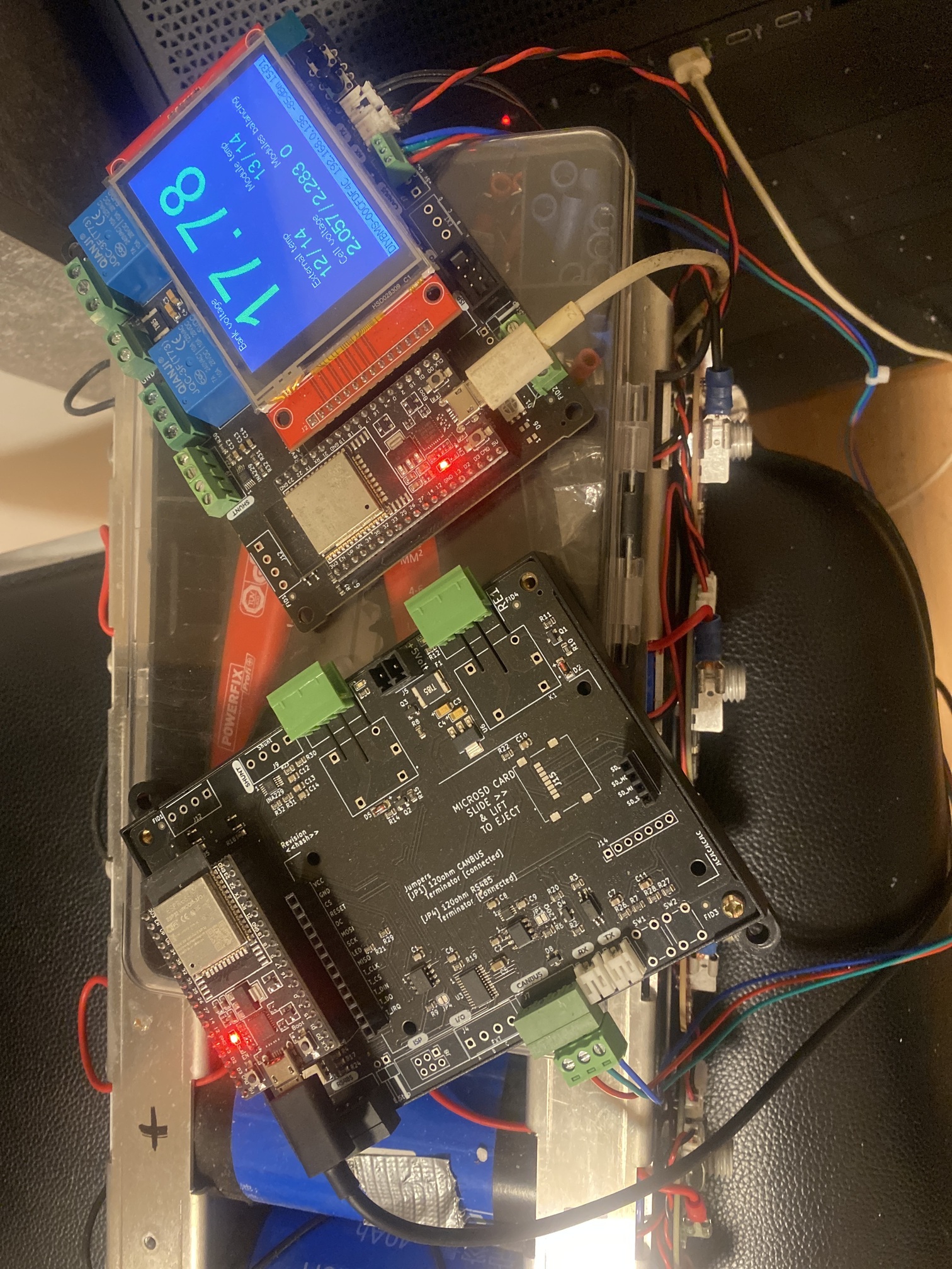
Only tested on the test station, not fully tested.
This upgrade only for testing
Important:
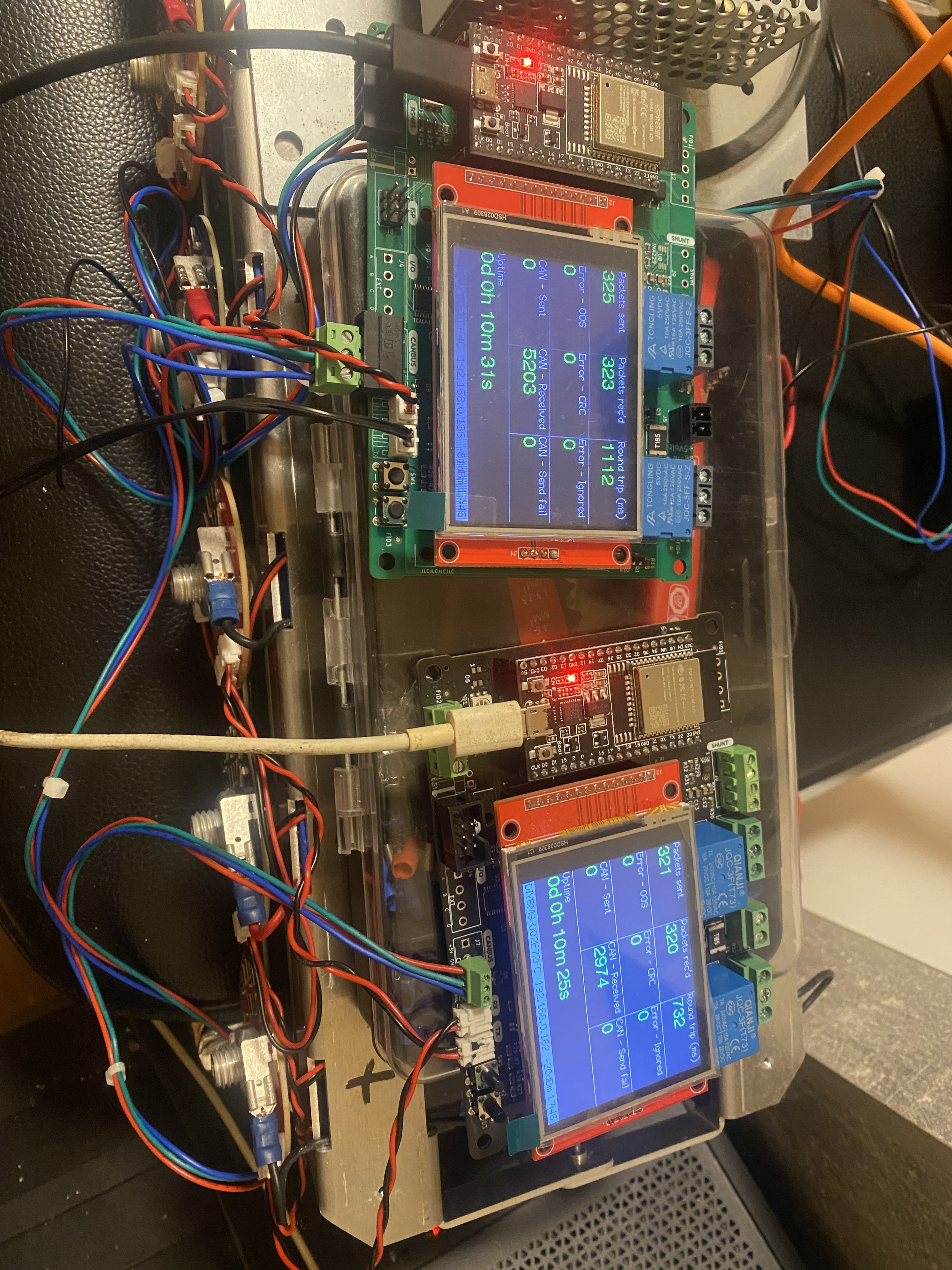
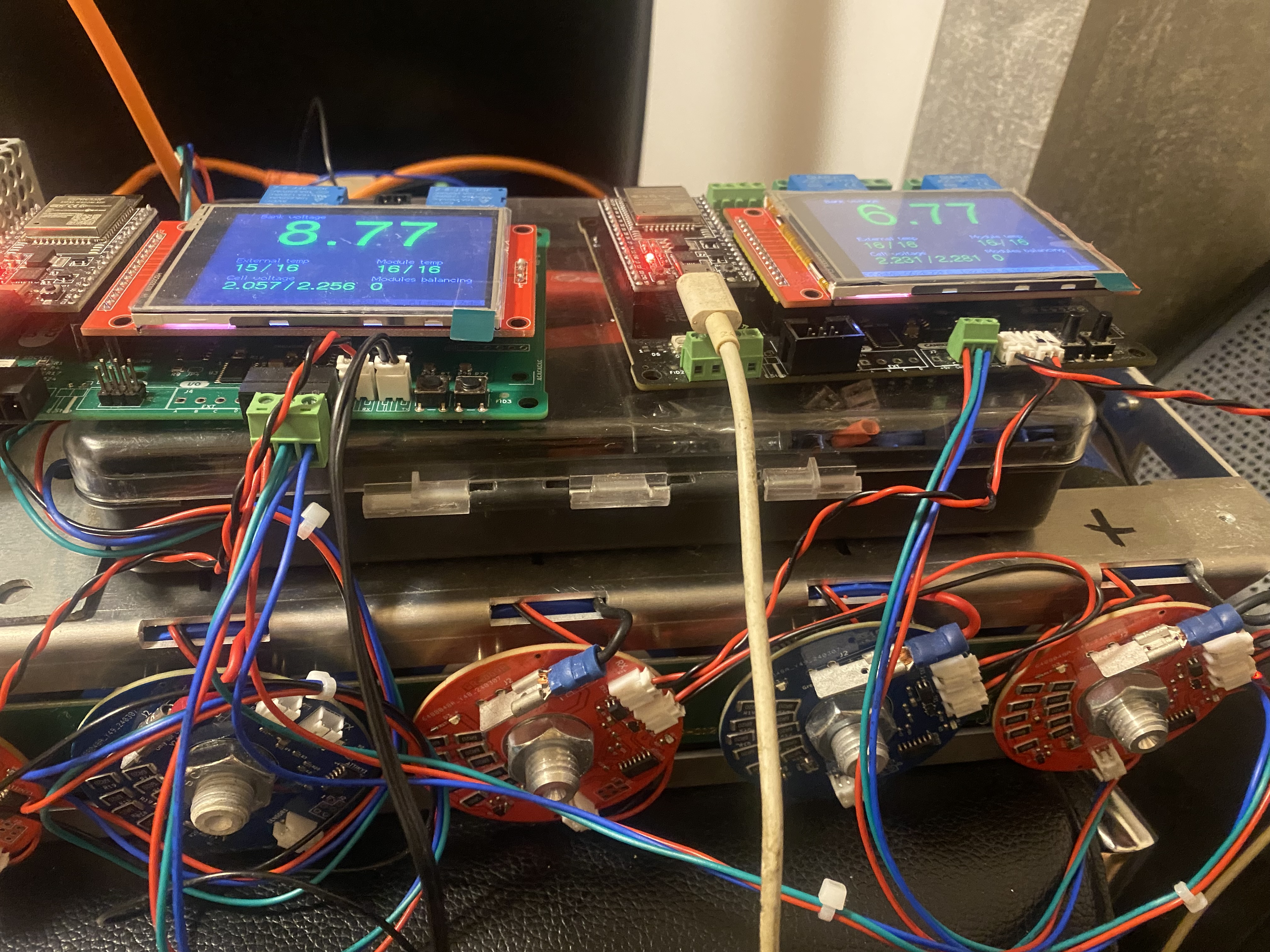
.) The shunt must be used on the Master DiyBMS controller. First controller power on and automatically is this the Master all another controller are automatically slave you can max use 10 diyBMS connect all controller over Canbus cable with CerboGX
.) The Master controller is the first controller you power on.
.) All controllers can be Master or Slave automatically based on battery values.
.) The shunt must be in the Master controller, as this controller collects data from Slave controllers and sends it to the Cerbo GX.
I have implemented new protection functions.
After testing in production, I will post it here.
/*------------------------------------------------------------------------
*
* Project: PYLON TECH BATTERY Emulator for DiyBMS
* Using Canbus @ 500kbps and 11 bit addresses.
*
* Author: Trajilovic Goran (ZoMiGo)
*
* -----------------------------------------------------------------------
*
* Description:
* Manages communication between PylonTech batteries, DiyBMS, and Victron via CAN bus.
* Detects when a module requests "Charge Stop" and adjusts the charging current accordingly.
* Calculates and sends the corrected charge current (0x386) to Victron.
* Automatically detects failed slave modules and excludes them from charging calculations.
* Transmits highest and lowest cell voltages per module (0x381 + Module ID).
* Sends BMS identification (0x305) to Victron.
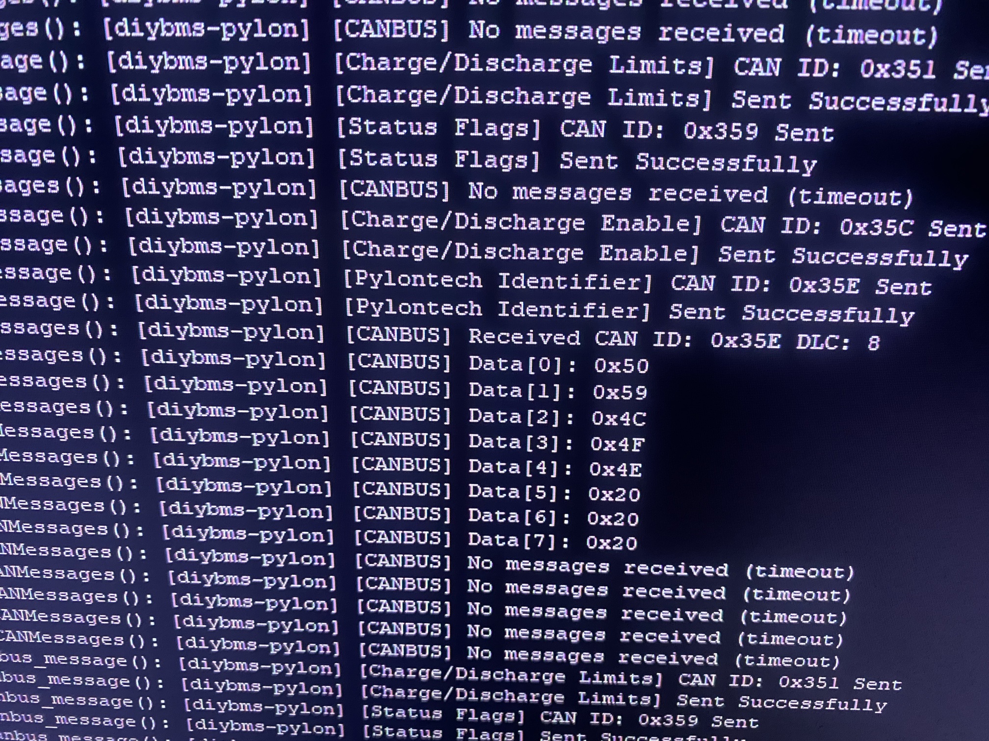
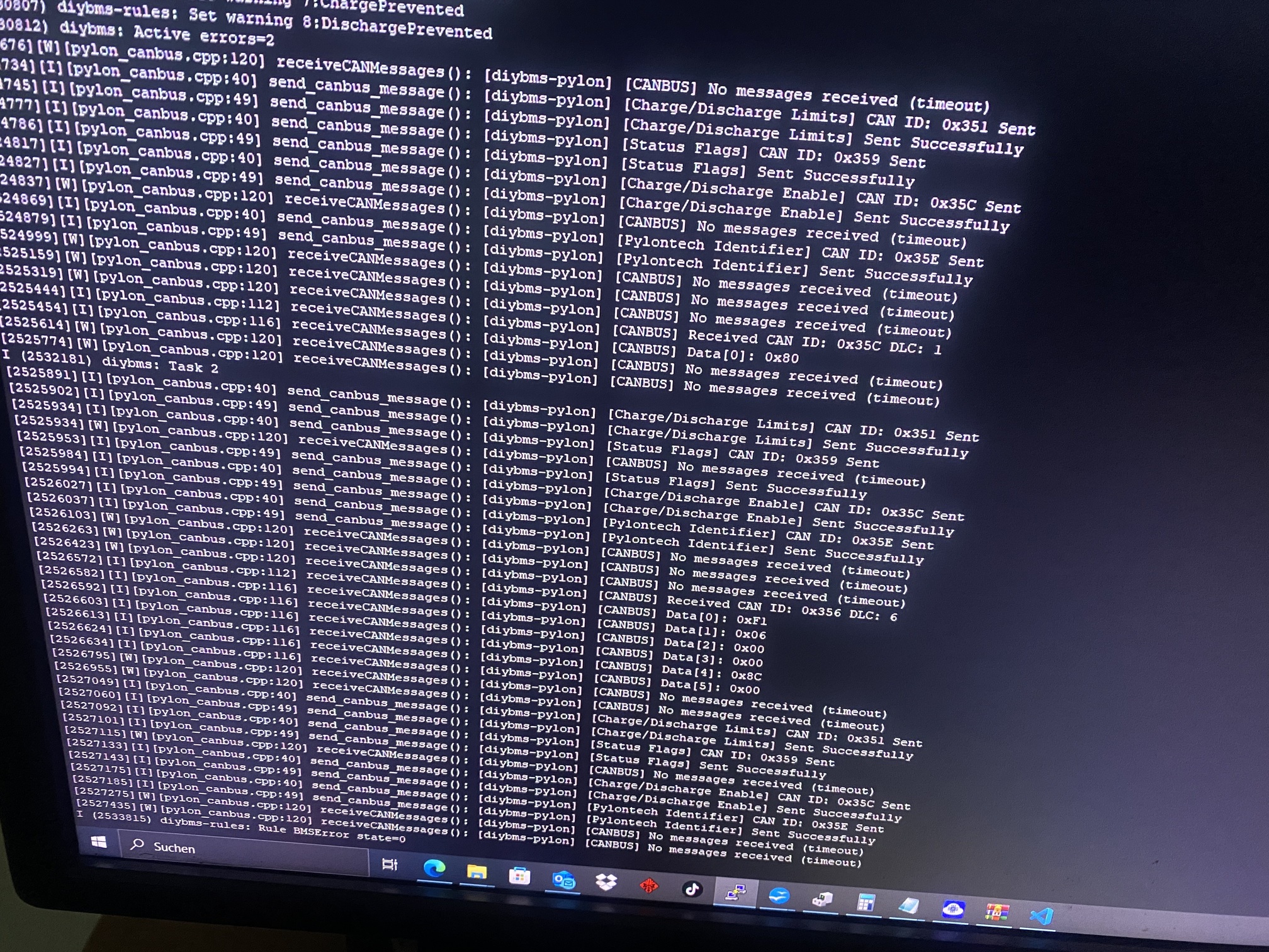
* Implements specific PylonTech CAN messages (0x351, 0x355, 0x356, 0x359, 0x35C, 0x35E).
* Ensures that Victron dynamically adjusts the charge current instead of abruptly stopping charging.
*
*/
#include "pylon_canbus.h"
#include "bms_id_manager.h"
extern uint8_t totalSlaves;
#define USE_ESP_IDF_LOG 1
static constexpr const char *const TAG = "diybms-pylon";
ConsolidatedData consolidatedData;
uint16_t lowest_cell_voltage_per_module[16];
uint16_t highest_cell_voltage_per_module[16];
bool module_charging_allowed[16];
// Sends BMS identification to Victron
void sendDeviceIdentification() {
uint8_t data[8] = {'P', 'Y', 'L', 'O', 'N', 'T', 'E', 'C'};
send_canbus_message(0x305, data, sizeof(data));
}
// Sends module voltages & charging status
void send_module_status() {
uint8_t data[8] = {0};
for (uint8_t i = 0; i < totalSlaves; i++) {
data[0] = i + 1;
data[1] = (lowest_cell_voltage_per_module[i] >> 8) & 0xFF;
data[2] = lowest_cell_voltage_per_module[i] & 0xFF;
data[3] = (highest_cell_voltage_per_module[i] >> 8) & 0xFF;
data[4] = highest_cell_voltage_per_module[i] & 0xFF;
data[5] = module_charging_allowed[i] ? 0x01 : 0x00;
send_canbus_message(0x381 + i, data, sizeof(data));
}
}
// Sends corrected charge current
void send_corrected_charge_current() {
int16_t current_charge = currentMonitor.modbus.current;
int16_t stopped_module_current = 0;
for (uint8_t i = 0; i < totalSlaves; i++) {
if (!module_charging_allowed[i]) stopped_module_current += 10;
}
int16_t corrected_charge_current = current_charge - stopped_module_current;
if (corrected_charge_current < 0) corrected_charge_current = 0;
uint8_t data[8] = {(corrected_charge_current >> 8) & 0xFF, corrected_charge_current & 0xFF};
send_canbus_message(0x386, data, sizeof(data));
}
// PylonTech CAN Messages
void pylon_message_351() {
struct data351 {
uint16_t battery_charge_voltage;
int16_t battery_charge_current_limit;
int16_t battery_discharge_current_limit;
uint16_t battery_discharge_voltage;
};
data351 data;
data.battery_discharge_voltage = mysettings.dischargevolt;
uint16_t default_charge_voltage = 1;
int16_t default_charge_current_limit = 1;
int16_t default_discharge_current_limit = 1;
if (mysettings.canbusinverter == CanBusInverter::INVERTER_DEYE) {
default_charge_voltage = rules.lowestBankVoltage / 100;
default_charge_current_limit = 0;
default_discharge_current_limit = 0;
}
data.battery_charge_voltage = default_charge_voltage;
data.battery_charge_current_limit = default_charge_current_limit;
data.battery_discharge_current_limit = default_discharge_current_limit;
if (rules.IsChargeAllowed(&mysettings)) {
if (rules.numberOfBalancingModules > 0 && mysettings.stopchargebalance) {
} else {
data.battery_charge_voltage = rules.DynamicChargeVoltage();
data.battery_charge_current_limit = rules.DynamicChargeCurrent();
}
}
if (rules.IsDischargeAllowed(&mysettings)) {
data.battery_discharge_current_limit = mysettings.dischargecurrent;
}
send_canbus_message(0x351, (uint8_t *)&data, sizeof(data351));
}
void pylon_message_355() {
if (_controller_state != ControllerState::Running) return;
struct data355 {
uint16_t stateofchargevalue;
uint16_t stateofhealthvalue;
};
if (mysettings.currentMonitoringEnabled && currentMonitor.validReadings) {
data355 data;
data.stateofchargevalue = rules.StateOfChargeWithRulesApplied(&mysettings, currentMonitor.stateofcharge);
data.stateofhealthvalue = (uint16_t)(trunc(mysettings.soh_percent));
send_canbus_message(0x355, (uint8_t *)&data, sizeof(data355));
}
}
void pylon_message_356() {
struct data356 {
int16_t voltage;
int16_t current;
int16_t temperature;
};
data356 data;
if (mysettings.currentMonitoringEnabled && currentMonitor.validReadings) {
data.voltage = currentMonitor.modbus.voltage * 100.0;
data.current = currentMonitor.modbus.current * 10;
} else {
data.voltage = rules.highestBankVoltage / 10;
data.current = 0;
}
if (rules.moduleHasExternalTempSensor) {
data.temperature = (int16_t)rules.highestExternalTemp * (int16_t)10;
} else {
data.temperature = 0;
}
send_canbus_message(0x356, (uint8_t *)&data, sizeof(data356));
}
void pylon_message_35e() {
uint8_t pylon[] = {0x50, 0x59, 0x4c, 0x4f, 0x4e, 0x20, 0x20, 0x20};
send_canbus_message(0x35e, (uint8_t *)&pylon, sizeof(pylon));
}
// Main loop
void loop() {
send_module_status();
send_corrected_charge_current();
pylon_message_351();
pylon_message_355();
pylon_message_356();
pylon_message_35e();
delay(5000);
}

starting-new-work.pdf (2.7 KB)
pylon-idea.pdf (5.2 KB)
RS485_Developer_Guide.pdf (5.9 KB)
diyBMSv4ESP32_Developer_Guide_Bilingual_Full.pdf (7.0 KB)
For those interested there is now a branch on Stuarts github with the firmware i have been working on. A few have been using with success but more feedback would be great. On the settings page for each controller you specify the total # of controllers and a unique integer (current max of 8). Selecting high availability will provide uninterrupted communication with the inverter if a controller is disconnected. Each controller needs its own shunt.
1 Like