Hello new user here,
I am finishing my Grid Tied solar install. I have been searching the site and the learning guides but i have a question. I have a grid tied solar install with microinverters. the Solar terminates in my breaker box.
I want to monitor using the emonPi and the two CT sensors.
I plan on placing one on the solar run before it reaches my breaker panel and the other from what i can read is to be placed on the house consumption.
My feed from the utility is a 200A single phase service. Would i be able to utilize the standard CT sensor included with the emonPi kit or would i have to find another CT sensor and calibrate it?
Would one or the other be more accurate?
If i haven’t included enough info please let me know or if this belong in another section. Thanks in advance.
No, you (most likely) cannot use the standard c.t. I say ‘most likely’ because you probably won’t get the shop one on your cable. I understand that in many cases you won’t be using the maximum current of 200 A, but there’s a good chance that could be taking more than 100 A. Ideally, you should size each c.t. to the maximum current that you will take (or generate).
There is a reasonably wide selection of suitable c.t’s listed on the “Use in N.America” page. All those will be more accurate than the standard ‘shop’ one, especially at currents above about 110 A. Note that most require a small resistor change in your emonPi.
One slight worry: Is your supply a genuine single phase, or is it the more usual split-phase (120 - 0 - 120) ? If it’s the latter, you need either c.t’s that you can thread the 2 cables through, or 4 c.t’s connected in pairs. See the N.America page again for details.
200 Amp service means he’s got 2/0 copper or 4/0 Aluminum Service Entrance Wires (incomers). Both are too large for the CT sold in the OEM Shop. (2/0 Copper OD is ~14mm, 4/0 Aluminum OD is ~ 16mm)
Granted, he won’t draw anywhere near 200 Amps, but he’d be mighty hard pressed to get close to 100 Amps, escpecially if he’s connected to a 15 kVA transformer (as are the vast majority of US houses) as the max current available from said transformer is 63 Amps.
If he’s connected to a 25 kVA transformer, the max available current increases from 63 to 104 Amps. Hovever, in that case, he’s sharing the transformer output with at least one, and possibly two or three other houses.
If his space heating is gas or oil, then his max load will be significantly less (vice electric space heating) as space heating is usually the number one electrical energy consumer in a typical US household. If he’s got gas heat, then his water heater, clothes dryer, kitchen stove and oven are quite likely to be gas appliances too, further reducing his max electrical load, as the electric version of those appliances are large 240 Volt loads. Electric water heaters typically consume 4500 to 5500 Watts, clothes driers roughly 6000 Watts. Central electric space heaters typically consume 10 to 15 kW. Electric baseboard heaters typically consume 1000 to 2500 Watts and a typical US house that uses them usually has one in several, if not all, rooms of the house. Typical stove elements consume 3 to 5 kW, and oven elements, 3 to 4 kW.
It sounds as if I have the same setup he does i.e. 200 Amp service and a microinverter based PV system. The microinverters use the hot legs to backfeed the circuit breaker in the load center. Even though the neutral is connected, they are 240V units. So I use three CTs. One on each feeder leg and one on the PV backfeed.
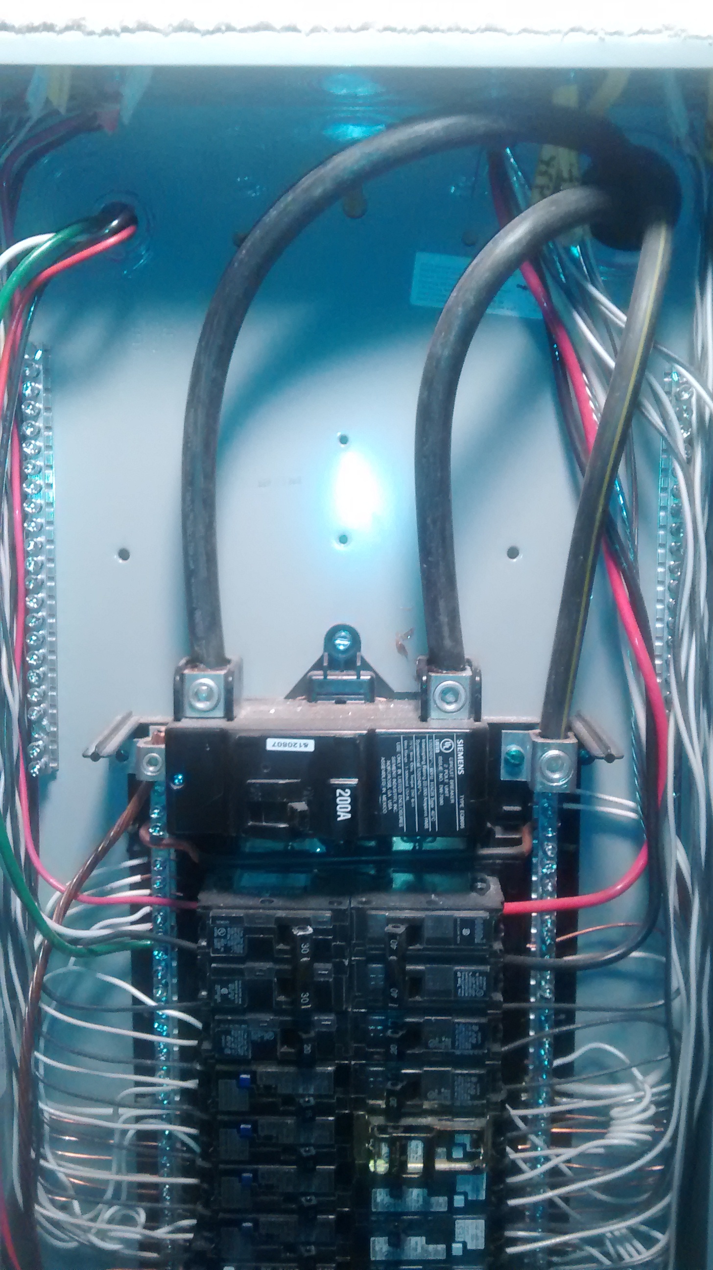
Thanks for the Help so far. I have pulled off the cover from my breaker panel for the details i have been lacking. My service looks like a 240V split phase with the neutral bonded to ground. it is coming in on Aluminum feeders. My solar arrays connect to the panel through a two wire back feed connected to a double breaker.
So i know i will be needing CTs sourced other places for the main feed. I have looked at the Use in North America page, from what i can read for the house feeders i can use 1 or 2 CTs depending on the space for the wiring and then to use the specified equation for the relevant choice. However it seems less clear on the back feed from the solar to breaker. could i use 1 CT there as well containing both hot lines or should i have 1 CT for each hot.
For CT choice on the house feed should i get the 1 or 2 CTs rated for 200A each or 100A apiece? I planned on using the CTs in the oem shop for the feed(s) from the solar breaker.
You need to add up the total current you’ll be likely to draw worst case, per leg, to determine the current rating of the c.t. that you’ll need. For best accuracy and resolution, you want to get as close to, but above, that current
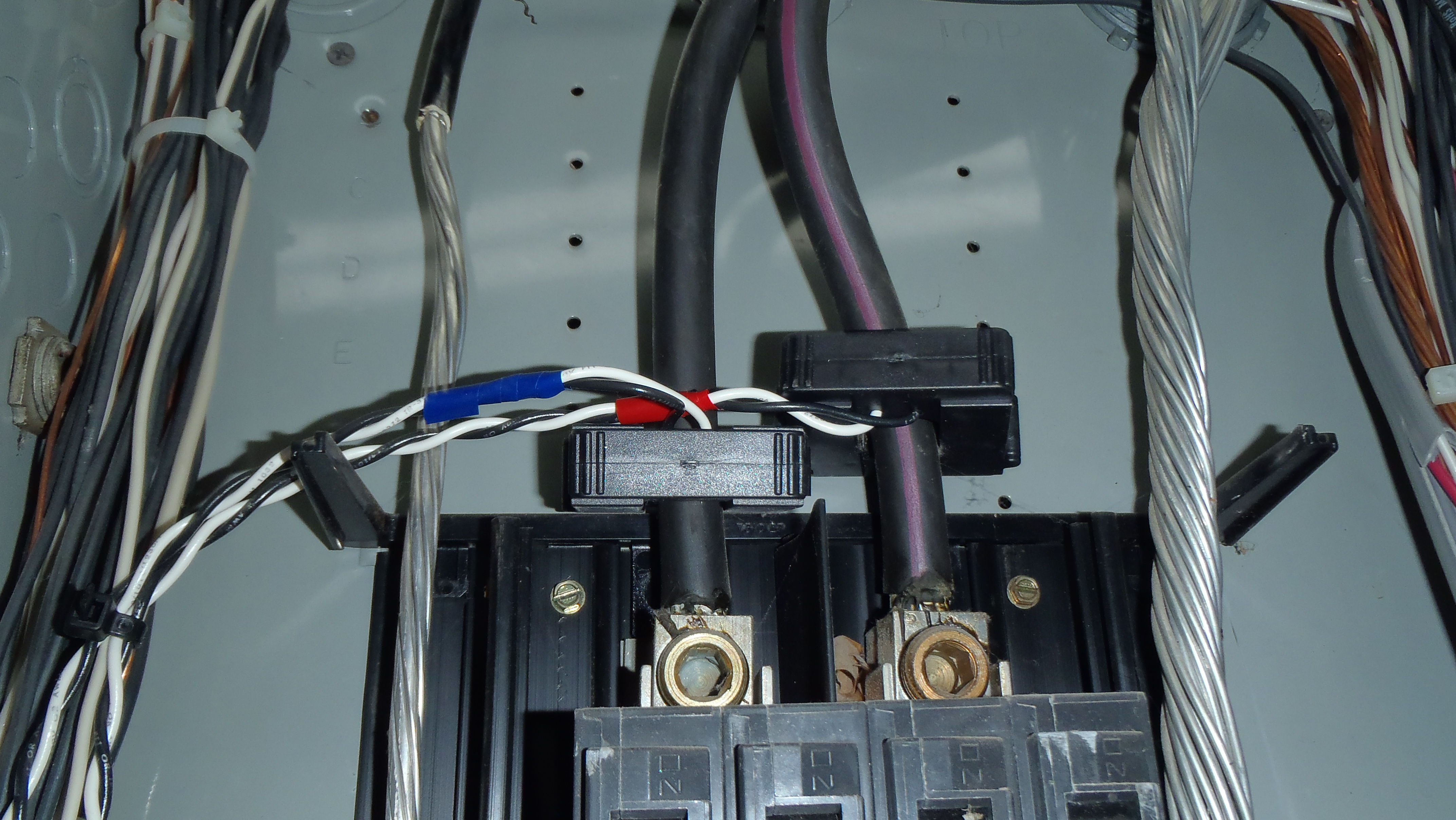
And you will need one on each leg of the incomer, as it won’t be possible to thread the 2 cables (upper picture) through 1 c.t. in the correct directions.
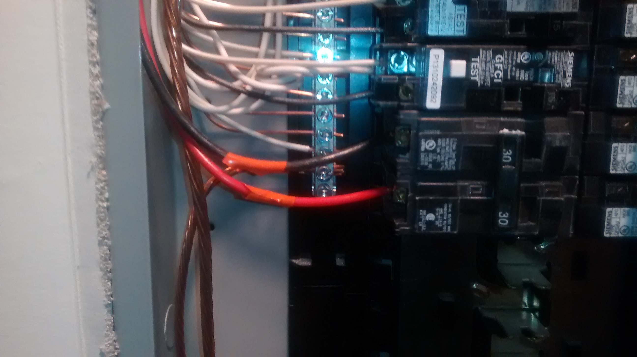
If the red and black (lower picture) is your 240 V infeed from the p.v., then it looks as if you have exactly the same set-up as Bill, so one c.t. on there, rated to the maximum current of your inverter, should be fine. The ‘shop’ c.t. is very likely to be way in excess of the rating that you need, which will be around the breaker rating at 30 A, so you’ll be using only ⅓ of the range. You could buy the 30 A : 1 V version (not from our shop) and remove the burden resistor, or you could buy the shop one and change the burden in your emonPi, or you could buy a different one (and still you’ll probably need to change the burden resistor).
BTW Justin, only one of the backfeed wires coming from your PV system should have red tape on it. i.e. one should be red and one black, like the top right breaker in your utility feed photo. (no need for the red tape on the red wire, and the black wire shouldn’t have any red tape on it)
Here is the CT I use for monitoring my PV system. 10 bucks cheap from Sparkfun. It’s rated at 30 A and has a 15 mA output. Fits AWG 6 wire with room to spare.
I wish I had that much extra room in my load center!
I have the same setup, split phase incoming with a double breaker PV connection. Here was my solution: I used an EmonPi and three CTs.
For grid sensing, I used two 100A:0.5V Wattcore split core current transformers. I installed them per Figure 3a and connected them per Figure 5C on the “use in North America” page linked to earlier. I have copper incoming lines, so the window on those CTs might not fit your cables if you have aluminum. However, there was a lot of room to spare when I installed them.
For the solar feed, I used a Wattcore 25A:1V CT. Installed per Figure 3c. I have a 3kW solar system, so this is about double what I need, but as I recall, it was the smallest 1V CT they had.
All CTs were ordered through Byram Labs. It took about 6 weeks to arrive, but I wasn’t in a rush.
When I ordered by EmonPi, I said I didn’t need the default CT and in return, they removed the surface mount resistors, which was very kind of them.
I’ve been meaning to write up a full walkthrough of getting my installation up and running, but haven’t gotten around to it. There is a pretty steep learning curve, and many different options if you are in N. America. Hopefully this helps.
Thank you all for the help so far. Because of the 4/0 aluminum Feeders i think im going to go with AIM Dynamics Sensors for the incoming and im going to go with the sensor Bill mentioned on Sparkfun for my PV install. I plan on using the EmonTX with the EmonBase. Thanks so much. at this point i am waiting on my items to arrive. Do you have pointers on the appropriate calculations and selection of burden resistor?
I think this would be a cool idea for the Forum in general. Have a section or tag for walkthroughs and examples, or peoples implementations and designs.
If the c.t’s that you’ve chosen are listed on the “Use in N.America” page, then the burden value and calibration constant is listed there. Failing that, the values will have to be calculated according to the theory here.
You should base the calculations on about 1.1 V rms across the burden at the maximum current you want to measure. This value allows a bit of headroom to account for component tolerances.
The burden resistor value then follows from Ohm’s Law knowing the c.t. secondary current. Choose the next lower preferred value, then use that actual value to calculate the calibration constant.
Hmm, that’s kind of odd. If you have a 200 Amp load center, and if your wiring is to code, then your feeders should be a minimum of 3/0. As 3/0 is an oddball size, most of the time 4/0 is used.
I went back and checked my pictures and you are correct. I remembered the copper lug screws so I thought my feeders were copper. But when I looked closely, you can see a little bit of aluminum above the lugs.
Over here, it gets stolen! My friend in rural Scotland woke up one morning to no electricity. When he looked out of the window, the cables had been cut by thieves and were hanging down the side of the pole just outside his property boundary. They cut the feed to his neighbour also, but left that as those were aluminium.
[And yes, I can spell!]
No worries. I’m aware that you say Al-oo-MIN-ee-um to our uh-LOO-mih-num.
Copper gets stolen here too. The criminals are so stupid, they do things like trying to steal copper from a sub-station thinking it’s not live. Except it was. 30 kV…
It seems my friend’s thieves learned from his mistake, or somebody like him - they cut it on the l.v. side of the transformer and left the h.v. side alone.
But thieves have taken the earth cables and earth mats from substations over here, and that of course endangers everybody served by that sub.