It would be interesting (maybe mostly for me) to monitor the expansion valve stepper motor movements. As I understand it, they work on a sequence of pulses… 1,2,3,4,1 to open and 1,4,3,2,1, to close.
If i were to pick out say pulses 1 & 2, then … IF pulse 2 is positive, X miliseconds after pulse 1, then this is an opening pulse. If pulse 2 is zero, X miliseconds after pulse 1, then this must be a closing pulse. Is this familiar to anyone?
An alternative method would be to use a quad op-amp as voltage-follower to take the 4 pulse wires, and drive another old valve (It may be risky to try driving 2 valves off a circuit designed for one). Then to cut open this second vale and graft a variable resistor pot onto it. From this, I could get a voltage to monitor. It would probably give a good-enough idea of how the valve is performing. I could manage the 2nd option, but not the first option.
I assume the valve shaft doesn’t make it to the outside and is visible?
A stepper motor only understands movement, not absolute position, so there is usually a mechanism where it ‘knows’ (or can assume) it’s at the end of its travel - either a limit switch at one end (or possibly both), or there’s not enough torque (i.e. current) to cause damage and the controller just carries on driving until the ‘brains’ can assume the valve position. It might not be necessary to ‘know’ the absolute position if it’s inside a control loop, which it clearly is.
If you count pulses and direction, and unless relative movement – or more specifically, the commands for relative movement – is all you need, then you’ve got the same problem (and you’d still have it with your second motor idea). You know what the valve has been told to do, you don’t know if it’s done it.
I’d try very hard to get sight of the end of the shaft.
Thanks Robert… yes, all sealed in. … welded-in, so no chance of seeing it. I assume to gives a few extra closing pulses to make sure its closed, and to correct any ‘drift’. Yes… the ‘dummy’ valve idea would need the same end stop, but I’m guessing two valves would act the same.
I spent 45mins reading off valve positions every minute from the controller. It would be great to get this on a graph, even if its approximate. I’m guessing that if the valve gets pulses, it will always move…?? I will not be able to get further back into the control commands. I think I can only get the 4 pulses… I guess I need to observe them with an oscilloscope first.
Maybe, but you said yourself “a few extra closing pulses to make sure its closed”, implying the valve and its analogue – if you go that route – always behave the same. I think this is a case of it will probably work, most of the time but I’d never guarantee it.
The same would apply if you did it in software: two, or more likely four, opto-isolators on the stepper motor power, count up/down pulses into an accumulator would probably be easier than the buffer, a cannibalised stepper motor, pot and ADC into software to store/transmit the values.
(The up/down counting is exactly what your old ball mouse did with the pulses from the optical encoders.)
Before you get your 'scope out, it will be worth studying this How to Drive a Stepper Motor - Motors, Actuators, Solenoids and Drivers - Electronic Component and Engineering Solution Forum - TechForum │ DigiKey. It should help you to interpret what you see.
A rather more accurate (but simplified) physical representation of the arrangement of the coils and poles: Stepper Motors: Types, Uses and Working Principle | Article | MPS
And a photo of a real one, cut open: https://www.edibon.com/en/cutaway-stepper-motor
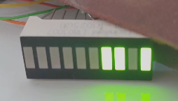
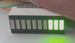
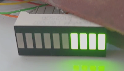
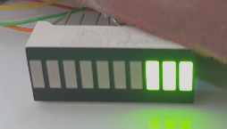
Thanks for the opto idea, dont know why I was not thinking that! So I have 4 x 510ohm resistors going to 4 LEDs. they sequence 1234 or 4321 etc I can easily count pulses, but need a clever way to look at what direction they are going… i.e. watch for LED1, and see what LED2 is doing a certain ms time after LED1 turn on…
This certainly shows it’s possible to extract some data, but I think you might need a higher frame rate. I’ve dropped that into a video editor (Kdenlive) and very few frames are repeated. However, what I see is these successive frames 1/30 second apart:

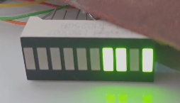
and then more ‘dark’ frames.
It looks to be fairly consistent at 8 frames per sequence.
I think if you can catch it going the other way, there will be a different sequence. Possibly a better way to see the sequence would be to get and connect the opto-isolators and feed the outputs into 4 digital inputs, and run as tight a loop as you can, reading the inputs in turn and recording the values against time - this should go a lot faster than your 30 frames per second video.
Thats a good idea using kdenlive. They are only connected by putting 500ohm resistors into the back of the plug… needs improving if the data shows promise. I was expecting 1,2,3,4,1,2,3,4 etc So far, only seen it opening at start-up. not caught it doing the odd ‘tweak’ when running. I need to keep looking.
One thing you should find out is which terminals are associated with each winding.
If you want to monitor the EEV the easiest way is to get access to the main control board of the heat pump. If I remember right you have new model of Mitsubishi Ecodan. The valve works with pulses but they are of the range from 0 to 300 ( 400 ) etc. The exact parameter is EEV possiotion - range from 0 to 300 (400). It depends of the EEV and how sensitive it is. Some heatpumps like Samsung have access to this parameter ot the display of main control board.