Please, tell me more. I have tried this on several occasions without success.
I used an emonTH v2 with one of these:
https://uk.rs-online.com/web/p/hall-effect-sensor-ics/8855388/
I have a 100 kohm resistor between GND and pulse input and a 10 nF cap between GND and vdd. I extended the sensor on about 1ft of flying lead and used a multimeter across the resistor to find the ideal location for the sensor (currently held in place with tape) where the voltage across the resistor drops from ~2.4 V to 0 V for about a quarter turn of the dial. When my boiler is running at full (heating/hot water) I get about 5 turns of the meter per minute which works out at about 30 kW power. So when I run the gas hob I get about one turn every 2 or 3 minutes, so the power consumption looks like a 6 kW sawtooth when in reality it should be ~2-3 kW constant load. Not perfect, but a big step forward on twice monthly meter readings.
Let me know if you need any more details.
Please!!! What sort of meter do you have?
I’ve got a strip of them sitting here!
That is where I start to get lost. Capable of following a wiring diagram, but what the bits actually are doing is a mystery to me.
I’d really want to use a Pi or a D1 Mini I have lying about.
Photos?
(I’ll split this to a new topic).
I’m interested in this too, but for reading my water meter.
Just checked eBay - wow. £3.49 each, or 10 for £4.20 from RS. Shame I only want 1!
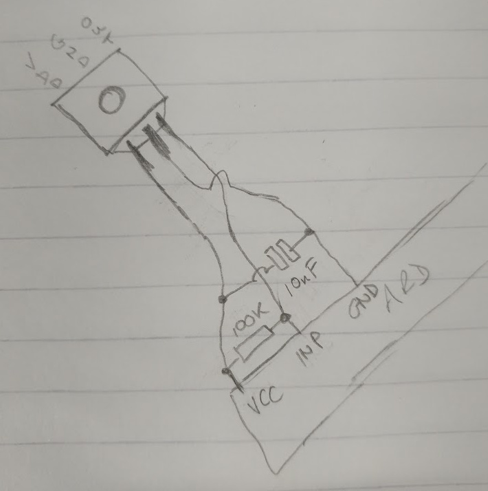
As for the circuit, is it something like this?
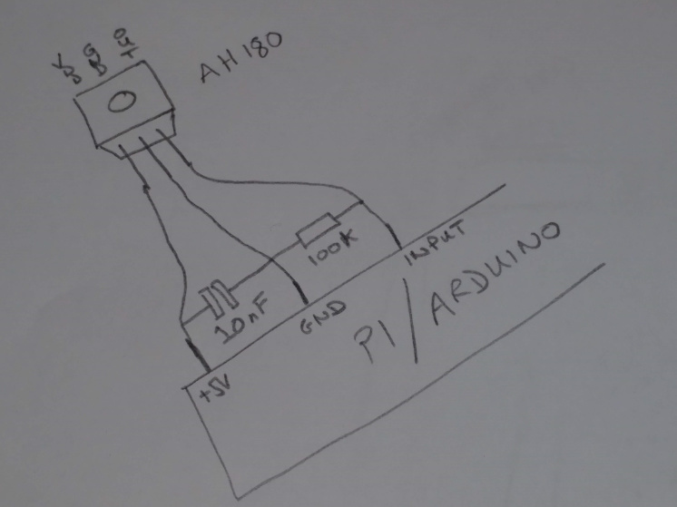
Does that take account of Pi inputs being 3v3 and not 5v tolerant? (yes I’ve blown a Pi input up…)
Hi Brian,
I’ve not built it, that was @cjenkins.
But looking at the spec sheet -
To support portable and battery powered equipment the
design has been optimized to operate over the supply range
of 2.5V to 5.5V and consumes only 24uW with a supply of 3V.
I’d say it would be fine.
You could buy 10 and sell 9 here at £3.48 each? 
The circuit looks wrong to me. Have a look at the data sheet: RS Components International
This shows the resistor as a pull-up and the capacitor across the supply for decoupling.
And the data sheet:
under Recommended Operating Conditions
Operating conditions: 2.5 V min - 5.5 V max.
Hi Lee, yes, sorry I got that. I also note he built it on an EmonTH so probably 3V3 input. It is one area I’d love to make work so I can see how much gas is needed/used for various situations.
Robert, you are as usual correct. ![]()
I was following @cjenkins description, where he’s (incorrectly!?) using a pull down rather than a pull up.
removed diagram to avoid confusion
Also, AH180’s going cheap, any one interested!? ![]()
Except you’ve now got your wires crossed!
[Edit]
If you look further down the data sheet, the reason for the capacitor across the supply becomes clear. It appears to turn on and sample the magnetic field for 100 (± 25) μs every 100 (± 25) ms, so the capacitor is there to ‘smooth out the edges’ and supply at least part of that current pulse.
1 Like