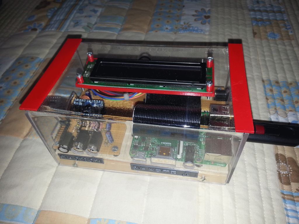
I have built a small test equipment that allows me to measure different devices and assess their consumption.
It’s based on the Arduino mini running an emonTxV3_DirectSerial sketch, a Raspberry with a USB stick running an Emoncms instance and a very basic LCD display connected to the Arduino. There are 2 CTs (SCT-013-000) and one AC voltage sensor.
Now, I’d like to measure the output voltage and current of a 230V/4A variac. I don’t see issues with the current.
The variable voltage could be a problem.
Question: do you think I could use the voltage sensor or is there any other practical solution?
I will follow your suggestion and put the voltage sensor on the input. That makes more sense and anyway the Arduino is already calibrated for that voltage.
One CT will be connected to the input and the second one to the output. The output current has to be monitored closely because you could easily overload your variac…
I am going to add a circuit breaker on the output as well.
What would you recommend? 4 amps? and which characteristic?
Thanks
The input to the Variac, or the input to your appliance under test? If you want the power consumed by the appliance, it should be the latter. Without measuring it, I don’t know what the losses of the Variac might be, but you don’t want to include them in the appliance’s power measurement.
It must be low enough to protect your Variac, but high enough to carry your test current for the required time. The closer you can get to your maximum test current, the better. Because the Variac has open windings, it’s probably more easily cooled than (say) a resin encapsulated device, but the copper will heat up more rapidly. I’d go with a standard “B” curve which is guaranteed to trip within 10 s at 9 × rated current, and will carry 1.13 × rated current more-or-less indefinitely. I think your Variac would not like 36 A for 10 - it would probably not be capable of that anyway, hence the comment about a lower rated MCB if possible.