We are having a Chelmer solar thermal/PV, wood stove and oil boiler solution installed which will use 2 x 500L thermal stores and a DWH tank.
My aim is to minimise oil use, and therefore I need to know when the thermal stores temperature drop to, or are dropping towards, a min temperature so I can load up the wood stove and save oil.
I envisage a display showing the various temperatures discreetly located in the living room near the stove, maybe colour coded so I can see if certain temps have been hit. Maybe an audio alarm. Also the same on my iphone/laptop with the ability to view temps over time periods.
I’ve been searching around for hours and cannot find the “out of the box” solution for this - I am not technical and cannot build anything.
I;d be very grateful for any help how to achieve this.
It’s perfectly do-able but you’d have to become a bit technical to do it at a reasonable cost. I’m sure there are expensive commercial systems out there.
We have a thermal store with about 5 points where I read the temperatures using temperature sensors. Originally I did this using the emonTx which reads the PV and mains and also diverts excess PV to the immersion heater in the thermal store.
I switched this some time ago to an ESP2866 based system which now reads the temperatures but also manages the boiler which is used for backup heating of the store.
Admittedly I’m reasonably able to do this having spent time over the years learning about things like this, hardware, software etc.
You never know you might find it fun to have a go at building something. There are good examples of how to use an emonTX to divert PV to an immersion heater as wwll as monitor house power usage and PV generation. I used Martin’s code - and there are versions of the code to handle more than one temperature sensor. You can easily set up a dashboard on the public emon server to display your data which can then be viewed from anywhere in the world.
Take a look at some of the tutorials etc. on the site - you might just find that you could manage to do it yourself.
If you buy an emonPi you can connect the temperature sensors to it. They are DS18B20s which are very accurate and you can string several together on the same cable.
I’m not an expert on how the emonPi manages the temperature sensors, i.e. do you have to do anything special to get the data from 5 or 6 connected sensors? Someone from the shop can help you with that - my system is home brew.
If you do go down this route you will be able to collect the data from the connected sensors and then with the openenergymonitor software (emonCMS) develop a dashboard showing the current temperatures. This is simply a web page, so can be viewed via a PC or smartphone. You can set rules against the inputs for example to notify you when a set point is reached etc.
Obviously if you have more than one temperature sensor connected you will also have to work out which input is which, there is a complicated algorithm to work out which one on the bus reports first but it’s easy enough to take one out of the sensor pocket in the heat bank drop it in a cup of coffee and watch to see which input rises to towards 100C.
The emonPi though is a bit of an overkill if you do not want to use the functionality to monitor power usage or PV generation. In a sense this is the primary use of an emonPi and the temperature monitoring is an additional function. Someone may be along later to correct my view on this but that’s the way I see it.
If your brother in law is more technically minded why don’t you get him to take a look at the emonPi and the software, or maybe call the shop to talk to one of the guys there.
I use thermal stores form my house heating I use evacuated solar tubes ( 7kw) and 7 kw heat pump… I have about 120 - 150 gallons of thermal store so every thing fairly automatic once things drop below 45C the heat pump comes on and then shuts off at about 48 C . on your solar thermal controller or atleast on mine they have addition for electric element which one could adaptor to turn on your oil furnaces and lower temperature alarms. if not you may want to look through their catalog of controllers and manuals you might find one that handles what you want it to do.
http://www.shuangri.com/en/ http://www.shuangri.com/en/download/Manual/
if I remember right they use to have one that controlled oil and pellet boilers and infloor heating systems
the controllers are not expensive I bought them for 50 - 90$ a couple years ago the 50$ handle generally one array- . heating element dump and cooling function and usually a circulation function generally have 3 - 5 sensors – the $90 ones usually handle two or more arrays and multiple tanks plus multiple pumps and 2 and 3 way valves and 4 - 8 sensors – just talk to peter wu he will set you up and he might even give you discount if you mention my name ( if he is in a good mood – lol )
but also as a thought does your solar thermal controller have a hot water line circulating feature - and you are not using it … you could simply wire that up – place the sensor on the tank and set your minimum tank temp the differential to shut off. and use that to alert you by light or buzzer or both or even turn on your boiler .
Simon, thanks very much for your advice. You have pointed me in the right direction. emonPi feels right as I suspect I will want to use other functionality over time.
Serious newbie question. How’s best to attach the ds18b20 to an insulated tank? Cut away some insulation, glue with some heat conducting glue, and then replace insulation? I am not sure if my tanks have been built yet, so I will ask manufacturer to install if possible.
Then if I want to install more temp. sensors remotely I can using this:
and indeed if I want to connect multiple ds18b20s to a emonTH then I can by following this:
Very often these large tanks have sensor ‘pockets’ (basically a small hole to insert the sensor into). If not it is very difficult to get accurate temperature readings. As an example, I measure the temperature of the boiler return temp by attatching a sensor to the outside of the pipe using aluminium tape under thick insulation. This reads about 8 deg less than the sensor in the tank pocket reads which in turn is the same as the boiler external temperature guage returns.
Agree. Get plenty of sensor pockets spaced equally up the tank. Most insulated tanks come with them anyway.
I have some attached to the pipework. Cable tie, then insulation over the pipe. It actually doesn’t matter that it may read lower than a sensor in a pocket, it’s about what’s going on over time and setting set point for controlling other heat sources can be done whether the temperature is accurate or not, so long as it follows what’s going on in the tank. So you need to get some data recorded so that you can see what’s happening under different circumstances and then start to control other things based on that knowledge.
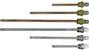
if you do not want to place sensor on the out side of the tank between the tank and the insulation ( perhaps it is fiber glass tank) or buy a probe and insert. if no probe port just add a T to you input or output then insert probe – or just make a probe it easy to make
I made probes from 2 inches long ( inserts into T fitting) to 5 feet long
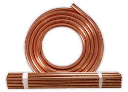
just buy some ACR tubing smaller then 3/8 10mm something your probe sensor fits in relatively close fit
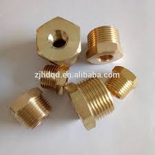
and some brass fitting either pex or reducer coupler ( dn 20 or 3/4 ntp ar the usual sizing but some are dn 15 1/2 ntp )
buy a reducer that internal thread diameter is slightly smaller then your acr tubing - bore the hole out to the same size as your tubing… add a little solder paste to the tubing insert into reducer and solder tight . then either crimp the end or buy a cap and solider tight again
If the thermal store is an off the shelf item they might not want to add sensor pockets. Also, although Stephen’s diy method would work fine, you will probably void any warranty by making holes in your tank. It can also be difficult if the tank has thick foam lagging which it should if it’s a thermal store.
I think you’ll probably find that the manufacturer will install thermostats to provide their control system, these are mechanical devices where you set a temperature on the thermostat and the device turns on or off an electrical connection. My tank came with these and it’s not possible to add another sensor into the same pocket.
So you’ll need to either have additional pockets installed by the manufacturer or use any spares they may have installed and use external connections on the pipework to install your ds18b20s. As I said in an earlier post, the temperature read by an external connection will not be as accurate as one taken from a sensor pocket at the same location. But… the readings will move up and down in sync with the temperature in the tank at that point, so all you need to do is to observe what is happening with the tank temperatures over time and decide on any action to be taken when certain conditions are reached.
It doesn’t matter if a temperature reading is a few degrees below what it would be if it were read from a sensor pocket. What matters is that a temperature has been reached where an action needs to be taken.
Hope I’m making myself clear with that explanation.
Just to be certain, my home brew control system reads temperatures in 5 places in the tank, some with sensors in sensor pockets, some mounted on the pipework close to the tank. I let the manufacturers control system run for some time and then could see that when the control system decided that the tank was not hot enough and switched the boiler on (and then off) to boost the temperature I could follow that with a reading I was taking in the middle of the tank. This gave me the temperatures from the sensor at which I should be turning the boiler on and then off again.
In my case the reason I wanted to have my own control was that the control system from the manufacturer didn’t deal with the two scenarios we have with our tank, i.e. normal usage and usage when the central heating is on. In the latter case I want the tank to run at a higher temperature overall to deliver the right temperature into the central heating radiators. So I needed to know when the central heating was on and manage the supplementary heat from the boiler in accordance.
HUMMM?? sorry Bramco – BUT “void warranty” by making holes in the tank ??? that’s a new one one does not make hole in the tank you simply thread it on to existing inlet or outlet ports either directly or using a T fitting and if you have existing probe mounts ( sensor pocket - I will use the same wording as you to reduce confusion) you un thread those and make custom multi sensor pocket – if it happens to be 20 DN ( 3/4 ntp) and you are handy up can make sensor pocket that can hold up to 4- 5 individually sensors all independent of each other (If 15 DN (1/2 ntp) 2 -3 sensor pockets ). I usually make sensor pocket that have 1or 2- (sometimes 3 pockets ) on them one that is ~1 foot in length and another one that is ~5 feet in length that i insert from the top of the tank so that i can measure temps at both the top of the tank and bottom of the tank from one fitting.
Apologies Stephen, I took your method to involve tapping into the tank, which is obviously what you’d have to do if there weren’t any bosses available or you didn’t want to disturb the pipework on the outside of the tank supplied by the manufacturer - hence my thoughts about voiding warranty.
Given Will has already said he’s non technical, my thoughts were that he should try to get more sensor pockets installed, or if that can’t be done then to use sensors mounted on the pipework and utilise the readings from there, which will probably be a few degrees lower than a reading at that point in a sensor pocket but will still track what’s happening in the tank and allow for controlling what’s going on. Pragmatic, simple to excute and non invasive.
that why I suggested he use the hot water recirculation function on his solar hot water controller (if he has that function on his controller most do)then trying to build a controller he could do what he wants easy enough that way he would not have the data tracking but he could set up automatic boiler and warning system fairly easy.
or from the solar controllers I mentioned above from their basic controllers these sections
SR81, SR258 etc
CIRC DHW circulation pump controlled by temperature and time
or
THET Timing heating
or from the example of the ones that control boilers and other heaters systems
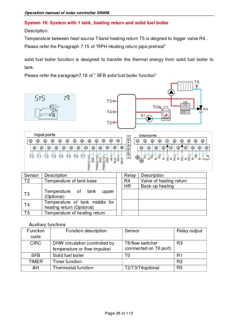
ie SR658
Minor update from me - thanks for all your advice.
Chelmer are installing sensor pockets into the tanks in parallel with the ones they use for their control thermostats. I will then install ds18b20s in each of these locations - 6 in total I understand.
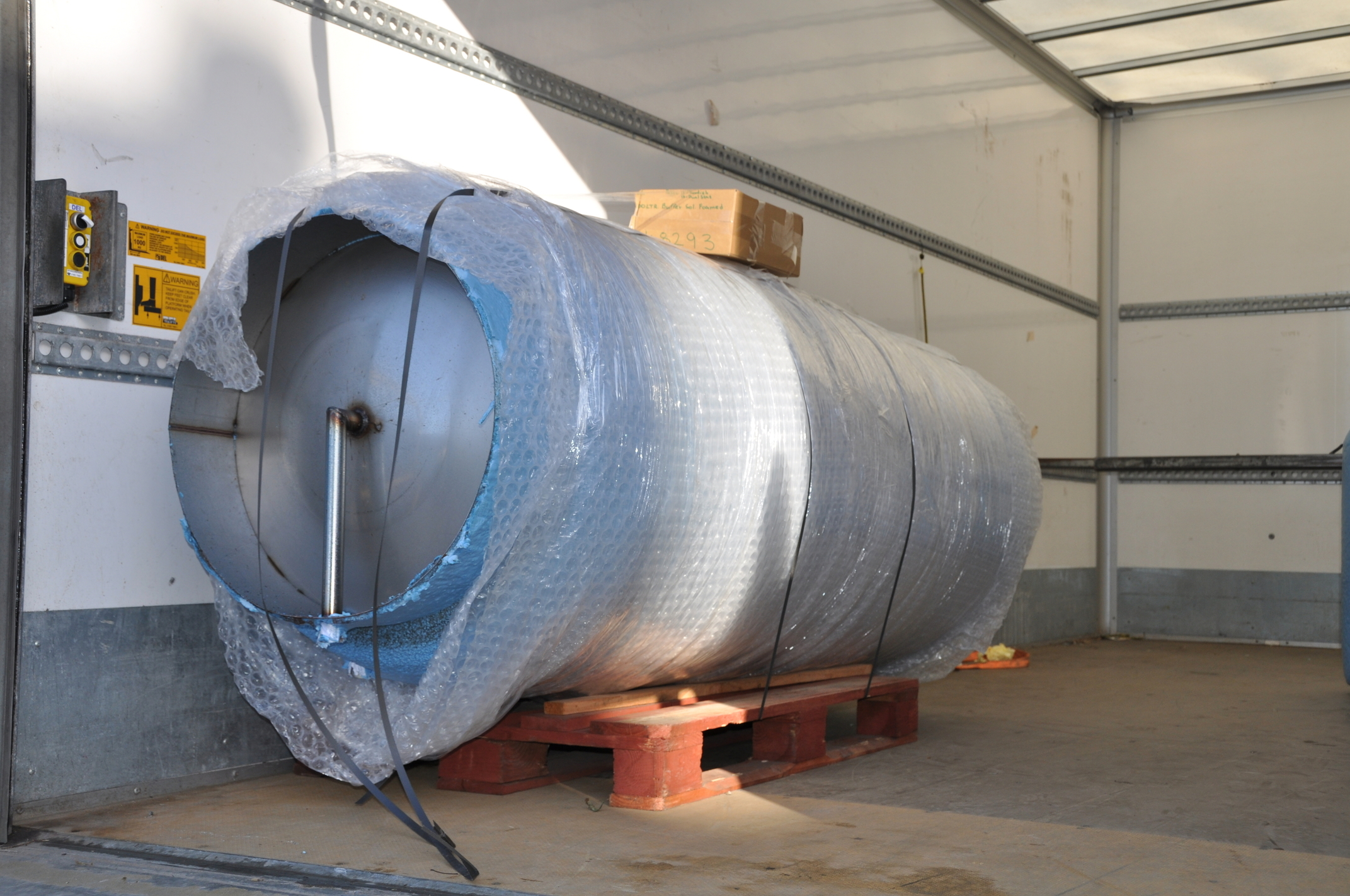
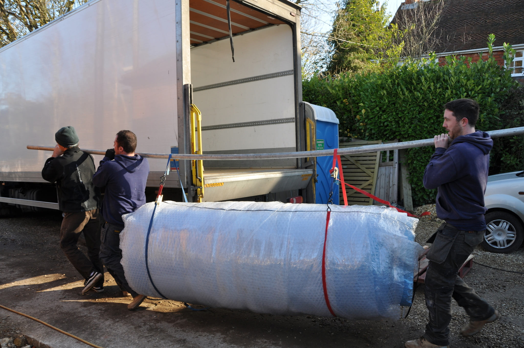
1000L thermal store and hot water tanks arrived today, after much spec change and delays. However good to see them on site. Still a few weeks away from commissioning though. I have learnt so much about the technologies in the last few weeks.
Time to order the emonpi and kit to play around with. I intend to build and test the whole monitoring solution off site, so I can transfer to the tanks once they are installed. No doubt I’l be back with questions!
A small update from me - to say thanks for those who pointed me in the right direction many months ago. I now have a number of graphs and dashboards I use for monitoring my heat systems, its all pretty easy to use once you get the hang of it.
2 questions about the system if anyone could help:
I am limited by the number of ds18b20 sensors I can string into one emonpi. I would like about 16. Is there a way to achieve this, simply?
I want to start experimenting with monitoring my solar PV. This is physically located about 50meters from my emonpi. I have ethernet connectivity between the locations. So I need a second emonpi in the second location? If so, how do I collate the data into one system?
Yes. You will need to change the sketch inside the emonPi.
Not really. The change itself is very simple, but there are a few ‘gotchas’ lurking.
First, you’ll need to talk to your Pi with a remote desktop. In the Pi you’ll need to use a text editor (Nano should be installed) to edit the sketch, then you’ll need to compile and upload the sketch (Platformio is installed and officially recommended - but I can’t tell you how because I don’t use it), then you’ll need to ensure an automatic update of your emonPi does not overwrite your change by updating it (when you need to) with “Update RFM69Pi” (i.e. as an emonBase) and not using “Update emonPi”.
The change you need to make is in the file scr.ino, and in the copy I have it’s line 103: const byte MaxOnewire= 6; // maximum number of DS18B20 one wire sensors
Change the number to, in your case, 16. You do need to be careful with how you connect the sensors in order to avoid reflected pulses corrupting the data. There’s more in ‘Learn’ about this.
No, you can have an emonTx and send the data by radio to your present emonPi (which should be OK if you have a good clear line of sight), or you can use an emonTx Shield with an Arduino with Ethernet. All the data will end up in the same emonCMS system.