Dan,
The 3202 is a two channel variant of the 3204 and 3208, and examining the datasheet, has the same operational characteristics. There are a few things you might investigate to improve your results with the ESP8266/MCP320x combination:
The ADC uses a sample-and-hold capacitor to take a sample of the input voltage for conversion to digital. The sample and hold period using your code is 1.5 SPI cycles. For any desirable SPI speed, that requires special handling to get the capacitor to fully charge.
The datasheet talks to this point, and references figure 4.2:
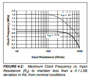
You can see here that as clock frequency goes up. the impedance of your bias voltage will need to be progressively lower in order to fully charge the S&H capacitor. The graph suggests that 1K is about the maximum. I have a hard time with colors on resistors but it looks like you are using 10K for the voltage divider. That will cause sag in your readings.
Those are a few things you can do to get excellent results given these limitations:
First, using an opAmp to produce the bias would completely solve the problem.
Another option is to use lower value voltage dividers, like 1K.
Adding a 10uf capacitor between the ADC input and ground will also help to “jump-start” the S&H capacitor.
Another approach is to use a technique I developed to increase the S&H hold while still maintaining a high SPI clock. It involves splitting the transaction into two. Here’s a link to a post about it: https://community.openenergymonitor.org/t/esp8266-wifi-power-monitor/1692/19?u=overeasy
You’re right that there is a subtle difference in the SPI transaction vs the 3204 and 3208, but the sample and hold period is defined the same way and the technique can be adapted to this variation in the SPI transaction.