Hello Brent,
I am working on an EV conversion as well and testing the DIYBMS for this purpose. Would be interested to know your opinion. So far the hurdle I’ve encountered is programing the modules and making the controller communicate with the modules.
Cheers,
Paul
I got into DIYBMS to use it in an EV battery as well, I have build smaller batteries to test it and in my opinion this BMS system i very suitable for large batteries, I would say there is no size limit. I have a BMS system in my EV right now that can do balancing at 200mA, DIYBMS can do balancing at 2A, it throttles down when warming up, but if you were to add fans I think it could be very suitable for very large packs. You can set up rules, so if one cell were to get too high voltage it can turn off the charging and wait for the balancing to get down the voltage off that cell and then continue the charging. If everything worked perfect it would be very good, I have had issues with the rules, making them a bit unreliable in some scenarios.
Hello Robin,
Good to hear you’ve made it work.
What versions of the controller and modules are you using?
I have controller V4.4 and module V4.4 but I have trouble making them communicate.
Hello Robin,
Thank you, I have posted the problem here.
There are some photos as well. I am going to redo the test and take detailed notes before describing the behavior. Briefly, I had this trouble since I first tested DIYBMS. Yesterday decided to give it another go, so uploaded the latest firmware (17-Apr-2023) and programmed a few modules with the latest firmware as well. I only connected one module at a time and test for communication. Unfortunately, the controller could not communicate with any of the modules. For a brief moment, after changing the communication speed from “standard” to 9.6k and restarting the controller via the webinterface, the controller showed the cell voltage. I disconnected the cell power, yet the controller was still showing the cell as it was still connected. After that the controller could not connect to the module any more. All the boards were made by JLCPCB. The only component I had to solder was the ATtiny841.
After I redo the test I’ll update this post. Thanks again Robin. PS. I live in Toronto, Canada; I might not be able to reply promptly because of the time zone difference.
Cheers,
Paul
Hi Paul, just looking at the picture I believe I see an issue, the wire from the controller seem to go from TX1 in to TX1 to the module, and then RX1 from module back to controller RX1. It should be controller TX1 (Transmit) in to RX1 (Receive) on the module and then TX1 module into RX1 controller. Try that and see if you notice any difference.
Hello Robin,
Yes, you are right, but this was just a silly mistake when I rushed to take the photo. I connect controller TX to module RX and close the loop via Module TX to controller RX. Sorry, disregard that photo. I’ll do some more work tomorrow and let you know. Thank you for your time to have a look.
Cheers,
Paul
Hello Robin,
Done, it is working now. I have updated my post where I mentioned my communication issues.
Robin, Brent, it looks like all 3 are planning to use the BMS in an EV, my suggestion is to keep in touch and exchange the learnings. It would help us all.
Cheers,
Paul
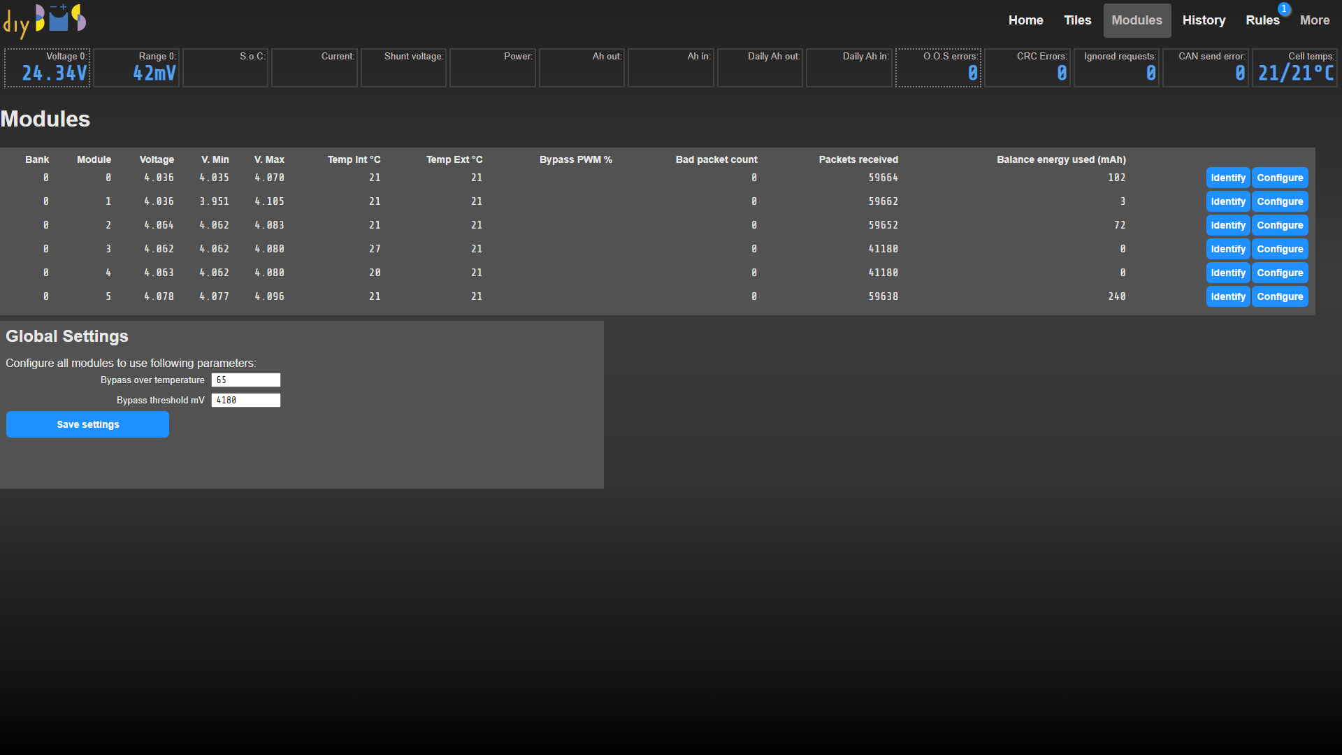
Here are my notes from the first test with 6 cells in series
Cells voltage between 4.1 and 4.14
The string was not connected to charge or discharge.
Connected the 6 cells in series and before connecting the controller to the modules, module #6 started to discharge the cell. Red LED went on and the resistors became hot.
Calibration of the modules. Last module (#6) was showing about 3.87 V (although at calibration I entered the value of 4.14V). Replaced the module thinking that it might be faulty, and then cell #5 changed to around 3.87 V.
Cells balancing. As 5 cells were showing above 4.1 V but one at 3.87 the BMS started to discharge the 5 cells. Trying to stop this, I changed the bypass treshhold to 4.18V. My understanding of the term bypass treshhold is the voltage that enables balancing.
Wi-Fi connection was not lost while testing, but noticed that the TFT LCD display stopped responding. After disconnecting and reconnecting the controller, the display came back to life.
After 14 hours, suddenly all cells were above 4 V. Balancing was disabled.