Marlec iBoost output power monitoring

Has anyone looked at the type of output that the Marlec iBoost has? I’ve read that it is PWM DC.

I’m looking to measure the power output so that I can control it by faking the CT input. My guess is that the iBoost uses a bridge rectifier followed by a high frequency chopper and inductor/flyback diode smoothing. If that’s the case then the output will be full wave rectified DC at variable power, with a little high frequency ripple on top. I could use 15A Hall current sensor ICs to measure the current.

I could measure the input using a CT instead, but that wouldn’t tell me which of the two immersion heaters is being driven.

Welcome, David, to the OEM forum.

No, but I’ve put some thought into the subject, and from a design point of view, this configuration makes life a lot simpler, even though the cost in losses is somewhat higher. One design I’d heard a fair bit of detail about does the switching at a.c, with the load fed by a.c, meaning the flyback ‘diode’ has to be a pair of active devices and timing between the series path and the shunt path becomes super-critical - overlap the conduction and you short the supply, underlap (is this a word?) and you leave the smoothing inductors open-circuit. Either way, something gets destroyed.

If the output is d.c, I think your suggestion of a d.c. coupled Hall effect device is the only realistic alternative to measuring the a.c. side with a conventional c.t. If the immersion heaters are “exclusive or”, then can you derive a digital signal to indicate which is receiving power - a neon across the immersion feed and a light-dependent resistor, for example?

But it doesn’t have to be a d.c. output to the immersion heater. If you (it’s hard to put this in words) connect the load and the a.c. terminals of the bridge rectifier in series, with the active switch shorting the d.c. terminals of the bridge, then your load sees a.c (kinder on the thermostat) and the switch sees only unidirectional current and voltage, and the flyback problem is simplified. Have you checked the actual output waveform? In this case you see a pwm chopped but probably smoothed a.c. wave, so the voltage amplitude changes. Note the neutral is then common to input and output, which it won’t be with your suggestion - this is likely the quickest way to check.

With either of these ‘d.c. switch’ configurations, you have probably 3 semi-conductor devices in series instead of one, hence the increased losses.

I’d suggest running a Spice simulation of both configurations so that you know the voltages and waveforms to expect.

One further consideration if the output is d.c, how are you going to measure the voltage to compute power and energy? You can’t use your Hall effect device because they cost too much current, and you have isolation problems with anything else.
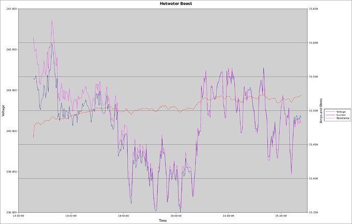
One possibility might be to measure the resistance of the element instead and thereby eliminate V from the calculation. Mine seems reasonably stable once operating. One way to measure that might be to briefly eliminate (disable?) the iBoost and measure and log power the conventional way (V and I) and do the division. When I do that on my 3600W nominal element, running flat out for almost an hour, it looks like:


V and I are measured while R is then just V/I.
I and R are both in the mid 15s so share the right hand axis.

If that’s not an option, a simple ohmmeter measurement across the element terminals might be accurate enough. When I do that on mine (when it’s not energised) I get 15.6R so not a million miles from the 15.5 I calculate once it’s running.

True, I wouldn’t expect a massive change in resistance from cold to hot, but there will still be a (hopefully small) variation.

Thanks for responding, both of you.

Yes, I was planning to measure the current only and use the known resistance of the immersion heater to calculate power.

Determining which immersion heater is powered may be more complicated than just measuring whether there is voltage across it, because the iBoost knows when the thermostat has opened (then the iBoost Buddy reports that the water is hot). So there may be a resistor supplying a small amount of current to the immersion heater in order for the iBoost to check the thermostat state when it is not supplying power. If that’s not the case and the iBoost only knows that the thermostat is open when it tries to supply power to the heater, then I could instead use a CT on the mains input and opto isolators to test which heater is being supplied with power.

Just joined the forum as I’m considering how to use my iBoost better. I’m on my third unit as the first two packed up and Marlec replaced them under warranty. The current one packed up too and I was ready to buy a different make but thought it was worth taking the top off to see if there was anything obvious wrong. There was - the mains input goes to a bridge rectifier that converts it to full-wave rectified DC, and one pin of this had an awful soldered joint which had managed to de-solder itself, probably because it had only a small amount of wetting so overheated. I re-soldered it making sure it was properly wetted, reassembled the unit and it was back in operation. I wasn’t impressed with the unit’s engineering or the company’s customer support.

I also took the time to have a look at the circuit and I could see no trace of an output DC-DC converter, just a couple of what I think are triacs (or could be SCRs since the output is DC). so I think the unit just supplies phase controlled FW rectified AC. They say in the documentation that the output is “specially modulated DC” which would check. This is presumably why the maximum cable length is limited to 3m, to avoid radiating too much interference from the cable.

The reason I’m now interested is that I would like to use the second output to feed excess power to a storage heater in the daytime, but the storage heater will be too far from the unit to directly connect it. I’m thinking of looking at the power waveform so see if I can figure out how to signal to a remote controller nearer the storage heater. Has anyone come across this kind of thing before please?

Welcome, John, to the forum.

I haven’t, but I’m wondering whether you could add a flywheel diode and a filter, now that the output is d.c., and still have a long cable. It’s not something I’ve seen, let alone tried - or even thought much about.

I think you’re probably right about the circuit configuration and the output wave shape. I presume no part no. was visible on the switching devices? They could still be power FETs chopping at a much higher frequency, but prompted by your other comments, a cheap and cheerful thyristor seems very likely.