Making the best of a Buffer

My new heatpump system was installed with a 25 litre buffer tank. I’m pretty sure I don’t need it, but at the time of quoting, the installer, and Vaillant seemed to insist on including one. I could have insisted myself to leave it out, but I’d probably have issues with the installer later if I needed help within warranty. Ultimately, I decided if I was to ‘prove’ the buffer’s effectiveness either way I’d include proper monitoring of both the ‘whole system’ and the ‘heating’ circuit separately, i.e. both sides of the buffer. I admit to being a keen follower of the whole COP/efficiency agenda (read: classic nerd who should get-out more) so I want to ‘tweak’ the system within given limits to come to a definitive conclusion as to whether a buffer on a singe zone ‘open’ heating system with sufficient volume has any benefits which justify its existence. If not, I’ll remove it, and the sec. pump, and take my COP ‘to the moon’ with the rest of you ‘bufferless’ lot.

This post isn’t about my decisions to date, my installer or Vaillant. It’s about seeking input to how I can make the setup work as efficiently as possible while maintaining comfort. As I suspect, the measured heating COP won’t be breaking any records, as I’m only using one electric meter which measures all input.

So, first question! Please see my system layout sketch:

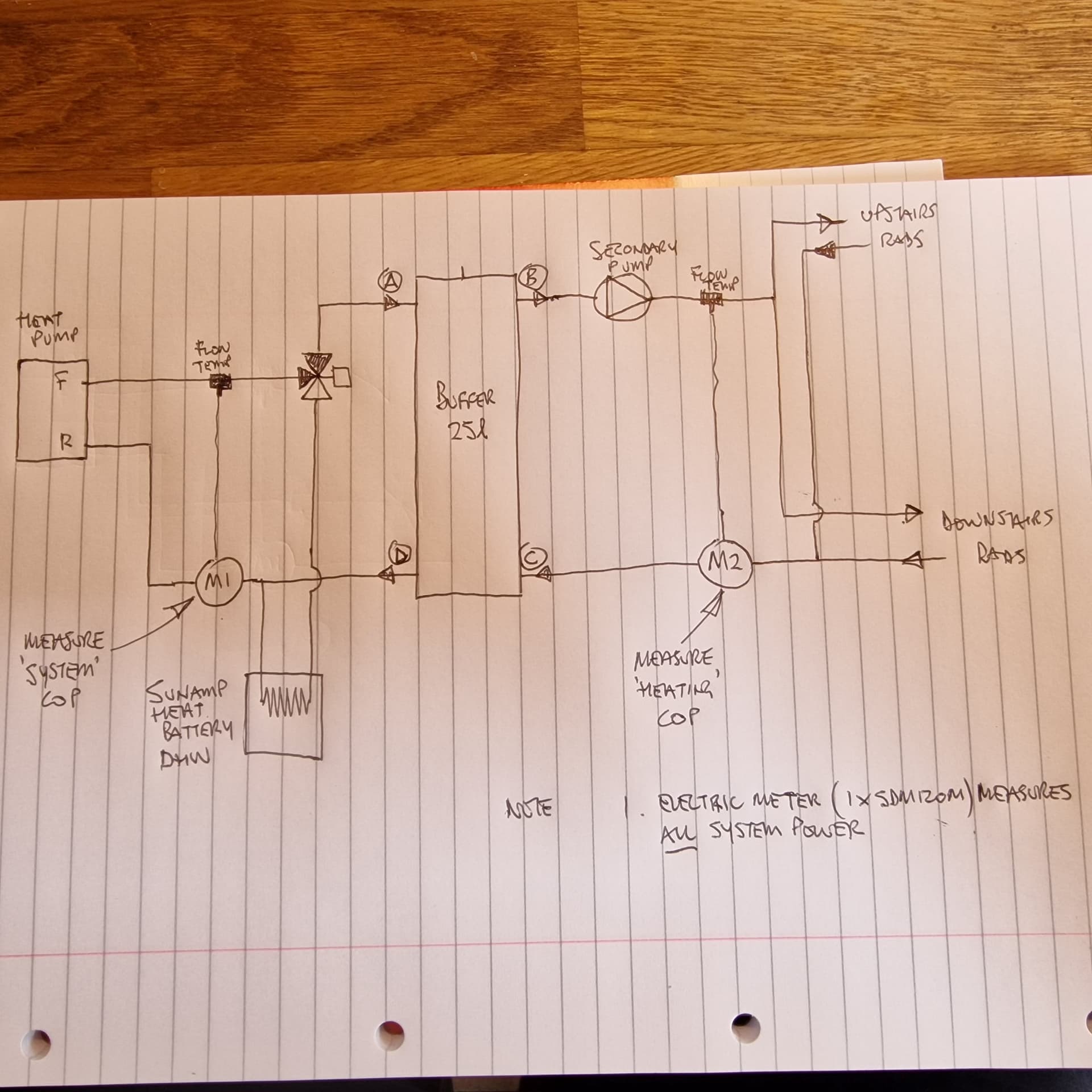
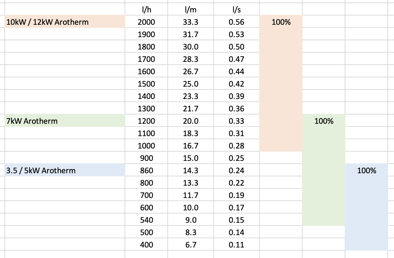
To minimise heat loss in the buffer, the flow rate in and out need to be matched (i.e. A=B, C=D on sketch). My secondary pump (Grundfos UPS3) is controlled by the Vaillant Arotherm+ 5kW controls, but only on-off. My understanding is that it has a PWM input to enable modulation, but it’s not currently used. The Heatpump’s (primary) pump is modulated by the control regime, but can also be ‘limited’ to a %value in the settings. Over the heating season I’ll be monitoring both flow rates and trying to get as good a match as possible, but does the assembled brains-trust have any ideas about how this flow-rate match can be better achieved? I will probably put together a temperature monitor (ESP32/ESP Home/Home assistant) to measure temps at A,B,C and D which will show-up how, and when circulation in the buffer occurs, and hopefully what happens in low-load conditions, i.e. below minimum heatpump output, and also during defrost cycles. My understanding is that the buffer, in steady-state heating conditions, even with equal flow rates either side, can’t be as efficient as ‘no buffer’ as the temperature at A will always exceed B, therefore loss. However, if the buffer becomes useful in low-load / defrost conditions, meaning the heatpump does less work, let’s see if we can quantify this using the monitoring.

Any input or comments so far, please?

I’ve included the ‘whole system’ monitoring on heatpumpmonitor.org and the secondary (heating) monitoring is linked in the notes from there, but here are the direct links:

Whole system monitoring
Secondary heating monitoring

It’s early days, so please disregard much of the historic measurements (to 13/9/23). Things will settle-down as we get into colder weather, I finish my radiator balancing and find the right weather comp. curve.

Cheers, Andy

2 Likes

My system installed last October was similarly plumbed to yours (but with a combination DHW and buffer split cylinder). Also two zones rather than one

Wasn’t performing great so moved from weather compensation to the Ecodan auto adaptation (which improved things) and then after discussing it with John Cantor, replumbed to make the system into a 3-pipe buffer. That was right at the end of the heating season but made a huge impact which will hopefully be evident this Winter.

3 Likes

I’ve had my system installed 12 Months now and was fitted with a 100L buffer tank in the attic, a pump either side which is PWM controlled. I didn’t have any monitoring on the system until the end of the heating season really. So was planning to see if heating performance was acceptable. Ideally I’d like it bypass it to see how much of an improvement I’d get without it. Though the company who installed the ASHP have advised my warranty would be invalid if I removed it. Which seems like BS to me.
I’m looking forward to your tweaking and findings as the weather get cooler.

1 Like

In reference to the original post, temperature A (i.e. HP flow) was always a few points above temp B whilst C & D were similar. Basically you are heating the buffer and the flow to the emitters was being diluted/lowered by the return temperature.

I’m monitoring all (and much more) on my local emoncms but only publishing some to emoncms.org as there’s a cost there eventually.

Changing to a 3-pipe system means A hits the emitters but you still get the benefits of larger volume etc.

I’m fairly confident my system will start to creep up the rankings over Winter though it will take some time given the lowly position it occupies now.

3 Likes

Thanks Deano and Nick - all good stuff and helpful.
I realised after the original post that I already have good monitoring of A,B,C and D temps from the two heatmeters fitted (duh!) albeit small distances away in well insulated pipework. So I have plotted these temps in Home Assistant / Grafana as part of the tweaking exercise. I forced the heating on yesterday after a drain-down / fix a persistent drip / refill and noted that both primary (Vaillant) and secondary (Grundfos) pumps settle to constant flowrates, at least for the time of the check.

As mentioned previously, I can’t easily adjust the Sec. pump’s flowrate except for switching between manufacturer’s modes which are too coarse. This pump will inevitably react to the CH system pressure drop, which at present is minimal as I have all rad. valves and lockshields wide open. This in anticipation of a balancing job when the weather’s a bit cooler, i.e. soon.

The primary pump in the heatpump is presumably controlled by sytem DT (etc), but can be limited by an installer level setting (can’t remember now the name) which as a % can be tweaked to match pretty closely the Sec. pump’s flowrate. A close match will minimise the buffer’s loss, so we’re on the right track.

However, (despite the nerd that I am) I’ll soon tire of making this adjustment, especially if/when the heatpump decides to modulate primary pump speed without my permission (!) Ideally I need to control the Grundfos pump using its PWM port, using the A-B temp difference (DT) as input. @deano mentioned a pwm controlled pump and I’d be interested to find out if a suitable pwm controller can be DIY constructed (ESP 32?) to achive this. I’m sure if a commercial controller is available it will be £££ so not an option as I’ll probably be ditching the sec. pump once my experiments prove I’m better-off without the 4-pipe buffer. In this case I’ll either ditch it or has been suggested convert to 3-pipe volumiser (the tank’s only 25 litres and sold as a volumiser anyway).

Readers who have got this far will be screaming “Ditch the buffer and pump now!” and I get it. However my knowledge-gap is in how a (well-behaving) buffer can be of benefit, albeit in a single radiator ‘open’ system with advanced weather compensation, perhaps in low-load conditions (i.e. below 2kW for my 5kW heat pump) and on defrost cycles. I think I’ve got sufficient monitoring to make a conclusion, even though we all know what it will be!

If any hydronics experts (@johncantor ?) can chip-in I’d be very appreciative.

Cheers, Andy

Both my PWM pumps are Grundfos and controlled by the ASHP controller. I did notice that the pump on the house side would overrun ? ( continue running when the ASHP was no longer heating). I bought some cheap temp sensors and monitored the 4 pipes of the buffer and this confirmed a 5-7˚C difference on both sides.

In the colder months I was getting continuous runs of 10-14 hours with the pump using circa 500w. At the time that seemed pretty decent (being new to the whole ASHP thing).

Radiators are balanced, house temp is set to 21˚C 0530-2300 and then 18.5˚C

1 Like

Thanks @deano - very useful to know. I assume your ASHP isn’t a Vaillant Arotherm+ if it can control both pumps via pwm?

I’m assuming the sec. pump’s overrun is to extract useful heat from the buffer, though of course it would have to recharge on the next cycle. Just a guess.

Interesting that the controller appears to manage a 5-7C DT across the buffer, rather than less. I think I heard that the sec. pump flowrate should be a little higher than primary (which would induce an A-B temp. diff) though I don’t know why.

I need to get to those long, steady heating runs to fully understand all this. No doubt soon enough, eh?

Cheers, Andy

I have an Acond Pro-N heatpump. It can control upto 5 pumps from memory. It has an option for swimming pool heating among other things.

Agreed, on defrost runs, the secondary pump doesn’t run.

I’m looking forwarder to the cooler weather and long heating runs :smiley:

My observation about the vaiilant internal pump is that it’s fixes itself on heating and adjusts the DT to maintain output.

Sometimes as low as DT2 when warm outside, upto DT5 when very cold.

Point in case this morning. No deviation with the flow rate, it just fiddles with the DT

So perhaps stick heating pump in Auto, see what flow rate you get shown in the controller (and heat meter?)
Auto will then give you a ballpark flow rate what the heat thinks is best.

edit: although will the arotherm just go super fast / max as there is no resistance just into the buffer and back? So perhaps this isn’t a great metric of what’s actually required?

Then try and set the flow rate on the other side to match that? I don’t think you’ll need PWM, just a fixed flow should be ok. (as that what the Arotherm sort of does)
You could always fix the heating side too to a % setting to really ensure things are the same?

I’ve found that no matter what you do with pump settings and speeds, the Arotherm just gets on with it and still cranks out the heat at decent COP (for me anyway).

What size Vaillant do you have?

Finally, I created this flow rate chart for the various Arotherm models, if this helps at all?

2 Likes

Thanks, Mick, good to know

When I ‘took over’ the installation after the installer’s efforts, I found that the secondary pump’s flowrate was much higher than the heatpump’s. As I see it, except for setting the secondary pump’s switch to the lowest flowrate (which it is), secondary flowrate can only be lowered by altering the pump’s head, i.e. closing lockshield valves. Now, I need to do a balance of my rads which will inevitably lead to higher system resistance and lower flow rate (unless the pump auto-compensates?). After the balance job, I’m hoping whatever the flow rate is can be matched by tweaking the primary pump % in installer settings. Whether or not this strangles the heat pump’s priority for DT and hence COP, we’ll see. Incidentally, this setting was originally set at 65%, probably default.

As I’ve said in another thread (or further up this one), my primary pump’s flowrate is measured on the heatmeter as around 22l/min, which is way higher than the 14l/min that Vaillant publish. I can only guess that the 65% default flowrate is somehow to equate to 14l/min. Dunno. Mine’s a 5kW Arotherm+, like yours.

Thanks again,
Cheers, Andy

The max 860l/h (14.3lm) is just how to get to 5kW output in mass flow
flow x dt x SHC

The flow rate can go higher. I’ve pushed my flow rate to almost 1200 (20lm) during hot water by choosing 100%. If there is little to no resistance it can just whistle around. Which is probably what will happen in and out of the buffer?

yes, from memory, 65% is default. But 65% speed down a 28mm pipe will be different flow rate compared to down a 15mm pipe.

So whilst you will use 65% or 70% or whatever, it’s more the flow rate get on the heat pump side of the buffer that is important?

If you were to try and work this out properly, i’m wondering if you could calculate the flow rate required on the heating side? By working out the index circuit (radiator with most resistance) by looking at the pipe sizes and bends/tees to get there. This is getting to the limit of the knowledge at the moment though!! :rofl:

But you (or your installer) would have to do these calcs anyway to ensure that the pump in the vaillant had enough head to serve the heating circuit if you removed the buffer and went direct. :wink:

Thanks for the interesting bits of information - I once saw a buffer tank distortion calculator online - does anyone remember where it was? thank you very much!

1 Like