Mains Voltage Monitoring and Optical Pulse Sensing Problems

In Jan 2024 I purchased a Single Phase 6 Channel Energy Monitoring emonPi2, with emonVs, CTs, temperature sensors and an Optical Pulse Sensor. It’s been up and running but I have 2 problems, that I would be grateful for some help.

Problem 1: Inconsistences in logged Mains Voltage

This is the main problem, that is limiting the use of the system, I would be very grateful with any help.
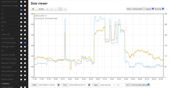
The monitored mains voltage from emonVs various significantly (~226 to ~257V), see yellow trace below), yet the mains voltage measured with a multi meter is around 238-240V, even when the monitored V jumps up to ~250V! This clearly results in incorrect power reading spikes, blue trace. (I appreciate accuracy will be lost when measuring low currents with a 20A CT, as below is monitoring a central heating pump. Note, the emonVs is plugged into a 13A socket.

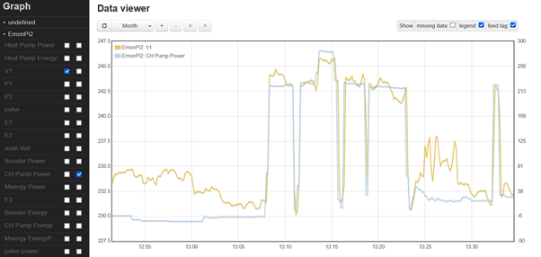
As can been seen below although it’s not an accurate power measurement, it does show the pump starting to switch on at 5am.

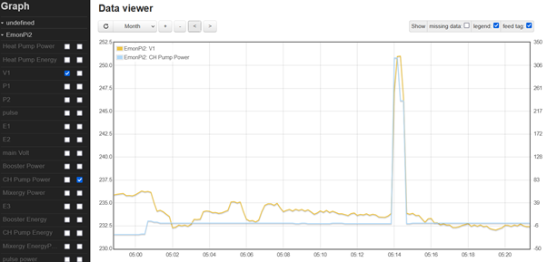
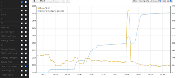
Below shows the main heat pump power and impact of the incorrect high V at time 5.14. i.e. it’s not just a problem associated with monitoring low power.

The high (incorrect) V values can last for several minutes, see below.

Problem 2: Optical pulse sensor not incrementing pulses
The optical pulse sensor monitoring my heatpump kWh meter (Emlite M22) does not result in ‘pulse’ incrementing, the pulse number only increments by 1 when I disconnect and reconnect the ‘data’ signal from the sensor. I’ve put a PC based oscilloscope on the signal from the optical sensor and have a clean 2V square wave but with a 10mS pulse duration. From reading info it appeared I needed to reduce the ‘pulse minimum period’ (pulse width). I’ve done this via the serial monitor ‘m 1 06’ and saved to EEPROM. Using the ‘list’ command ‘pulses = 1’ and ‘pulse period = 6’, hence this appear to have changed OK.

I note that when I go to ‘admin’ ‘serial config’ the page shows ‘Emon Tx4 Serial Config Tool’ (yet I’ve emonPi2). Looking at the emonPi2 user guide information under ‘CT calibration selection’ the screen shoot includes the following:

Mine only shows:

Help would be appreciated, so I can use the optical pulse sensor. Is my set up missing some firmware? or is there another reason.

Info from the ‘admin – system information’ page.

Welcome, John, to the OEM forum.

Problem 1.
I can’t think of a mechanism that would lead to a voltage varying both under and over the expected range except one, possibly two, manufacturing faults. And I wouldn’t like to say whether this is a fault in the emonPi2, the emonVs or both. I think you need to email The Shop ([email protected]) and simply refer to this Topic.

Problem 2.
As you’ve identified, the pulse debounce time was set too long. For the optical sensor, you should set the time to zero (it doesn’t, or shouldn’t, exhibit contact bounce at all).
For the pulse inputs to the ATmel AVR-DB processor, I documented this in the library supporting literature, it should have been repeated in the set-up instructions for your emonPi but I cannot see it anywhere. You write that m 1 06 effected a change so I think this is the pulse input you’re using. Therefore, setting the pulse minimum period to zero m 1 0 is your solution. Here’s what the library documentation reads (m 1 0 sets channel = 1 and period = 0):

void EmonLibDB_setPulseMinPeriod(uint16_t _period)
void EmonLibDB_setPulseMinPeriod(uint8_t channel, uint16_t _period, [uint8_t
_edge=FALLING])
Sets the minimum period of time that the pulse must be active and in a steady state to be
recognised, in ms. This must be shorter than the duration of the pulse. (Note: this differs
from the definition in previous releases, and if the period is specified, its value should be
reviewed.) For electronic switches that do not exhibit contact bounce, zero may be used.
The channel number (one-based) defines the input to be used, and must be specified if
edge is specified. Input channels for the emonTx V4 are: 1 – ‘Pulse’, 2 – ‘Digital’, 3 –
‘Analog-Input’ – alternatively the names ‘Pulse’, Dig’ & ‘ADC’ may be used. The
appropriate solder links must be made on the p.c.b, and the ‘Analog-Input’ pulse input is
not available when the extender p.c.b. (c.t’s 7 – 12) is fitted. The edge on which the pulse
is detected may be specified if required (RISING or FALLING). Default: period = 20.

That’s simple - the hardware and software are to all intents the same thing.
However, I’m afraid I can’t help you any further with the Serial Config Tool and CT calibration - I don’t have an emonPi2 to investigate. But I think it will probably respond to some if not all of the generic commands configuration and calibration commands described in this document (Note - I think the access code described is not needed.) General settings & calibration on-line.pdf (48.2 KB)
You do all of these exactly as you changed the pulse input setting.

Robert, Thanks for reply. I’ve changed the duration from 6ms to 00ms, but its not made any difference. I’ll e-mail the shop on the mains voltage issue.