I want to use an ESP8266 for the controller for PV diversion, and this has one ADC which I would use for supply current measurement. It strikes me that the mains voltage does not need to be measured accurately as it is reasonably constant in amplitude and waveform. It is only the phase of the voltage relative to the current that is needed to calculate the relative input/output power. So the voltage phase could be measured by a square wave derived from the mains voltage by simple zero-crossing detector as a digital input to the ESP8266.
I think Robin has, and you’re forgetting one important point - the fault level (i.e. impedance) of your mains supply. When you’re importing power and current, the supply impedance causes a voltage drop, so the voltage you see is lower than the voltage further back up the supply. When you’re exporting power and current, the same thing happens, but this time the voltage you see is higher than the voltage further back. So even though you can have the same current for import and export, the power will be different because the voltage is different.
Of course the accuracy of the power, or more strictly the energy, matters. Your objective surely is to neither import nor export wherever possible while surplus PV is available, and therefore you balance the energy consumed by your dump load against the potential excess.
So what accuracy is required? And I doubt that the impedance of the mains supply is important, as if it was significant there would be unacceptable losses in the power supply network. What value do you have for the impedance? 1ohm for example is surely too much? That would cause a 4V rms drop in supply for 1kW power. But the theshold for PV diversion is in the 10s of Watt range, so only ~0.04V drop and I doubt if that is important amongst the other factors. Normal supply variations are surely much greater any of these.
That’s for you to decide. If you’re happy with either a small import if you under estimate the PV generation and over-estimate your dump load, or a small export if your measurement is wrong the other way round, that’s fine. Robin’s Mk2 PV Router is able to maintain absolutely zero nett import or export over long periods - of course only while the dump load is capable of accepting the excess PV energy.
We’ve found that many commercial units are designed to have a ‘bleed’ of excess generation back into the supply, usually a couple of hundred watts - we think it’s so that import will never show on the customer’s meter whilst diversion is taking place. What of course they hope is the customer doesn’t notice that he is effectively losing that energy and not being paid, or paid only a small sum, for it.
You can of course measure your supply fault level, by putting a known load on and measuring the voltage drop. It won’t necessarily always be the same.
If you do implement your projected scheme, it will be interesting to see how close your energy balance is, and if it’s necessary to compensate for the varying voltage.
I’ve built the electronics and will test it soon. I’ll let you know of the results. I think that calculation of surplus power using a mains voltage square wave with accurate zero-crossings will be sufficient. The feedback loop of the system adjusts the diversion so that the resulting overflow is close to zero, independent of the absolute power measurement as long as it’s linear and in excess.
In any case the power measurement error over several cycles could be compensated by calibration, and as Robin says in section 7: Calibration: “… calibration of any Mk2 system with regards to power is generally not required, the measurement system just needs to be linear”… especially in burst mode.
Yes, but that statement relies on the flow of energy in both direction being measured correctly. With the Mk2 PV Router, the instantaneous AC voltage and current signals are measured alternately and their products are used to determine the energy flow. This approach to monitoring the flow of energy at the grid-connection interface is intended to mimic the operation of the meter as accurately as possible. The big difference is that the Mk2 provides an updated energy value every mains cycle, whereas the meter only lets you know when something bad (financially) has already happened.
Whenever a sizeable load is cycled on & off, the AC voltage level will flicker up and down as can be observed using any incandescent bulb. If surplus energy diversion is determined using only the measurement of AC current, it seems certain to me that exported power will be under-estimated and imported power will be over-estimated due to the step-wise change in the AC voltage levels. The net effect will be a small input of energy from the grid. With certain types of meter, that behaviour could result in significant charges being applied.
That unwanted effect could be offset by setting the parameter REQUIRED_EXPORT_IN WATTS to a small positive value. But the best way to achieve no net flow of energy to / from the grid is surely to measure both AC current and voltage.
For the latest Mk2 PV Router software, I recommend visiting the Downloads page of my website at Mk2PVRouter - Downloads
Thanks for the reply. However the AC voltage level change for high power loads will be very small despite what some may notice as flicker, since mains impedance has been measured at below 0.13ohm which causes only a 2V drop for 3.5kW switched, or less than 1% voltage error. I think this type of error would in no way affect the system operation, especially when compared to other errors in measurement.
I have already looked at the Mk2 PV Router software on the downloads page and found it very useful.
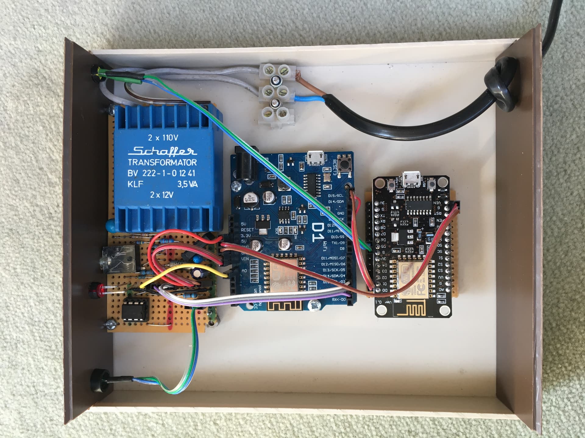
An update: I’ve successfully implemented the PV diversion system I described and it’s working well.
So it uses the one ADC in an ESP8266 to measure total net current flow and a digital (0/1) mains voltage phase measurement derived from a transformer followed by a zero-crossing comparator. Resultant power calculation is calibrated and is perfectly linear as it depends only on current flow. No filtering is used.
Interrupts from the 8266 timer are used to sample I and V accurately. Only 40 samples per cycle are used, fewer would also be accurate enough.
A remote ESP8266-based triac power switch is used via simple UDP messages sent on the local wifi network. The main box software is a simplified/modified version of the Mk2i v5. It also uploads daily surplus time to the Thingspeak internet site.
Thanks to all for the background.
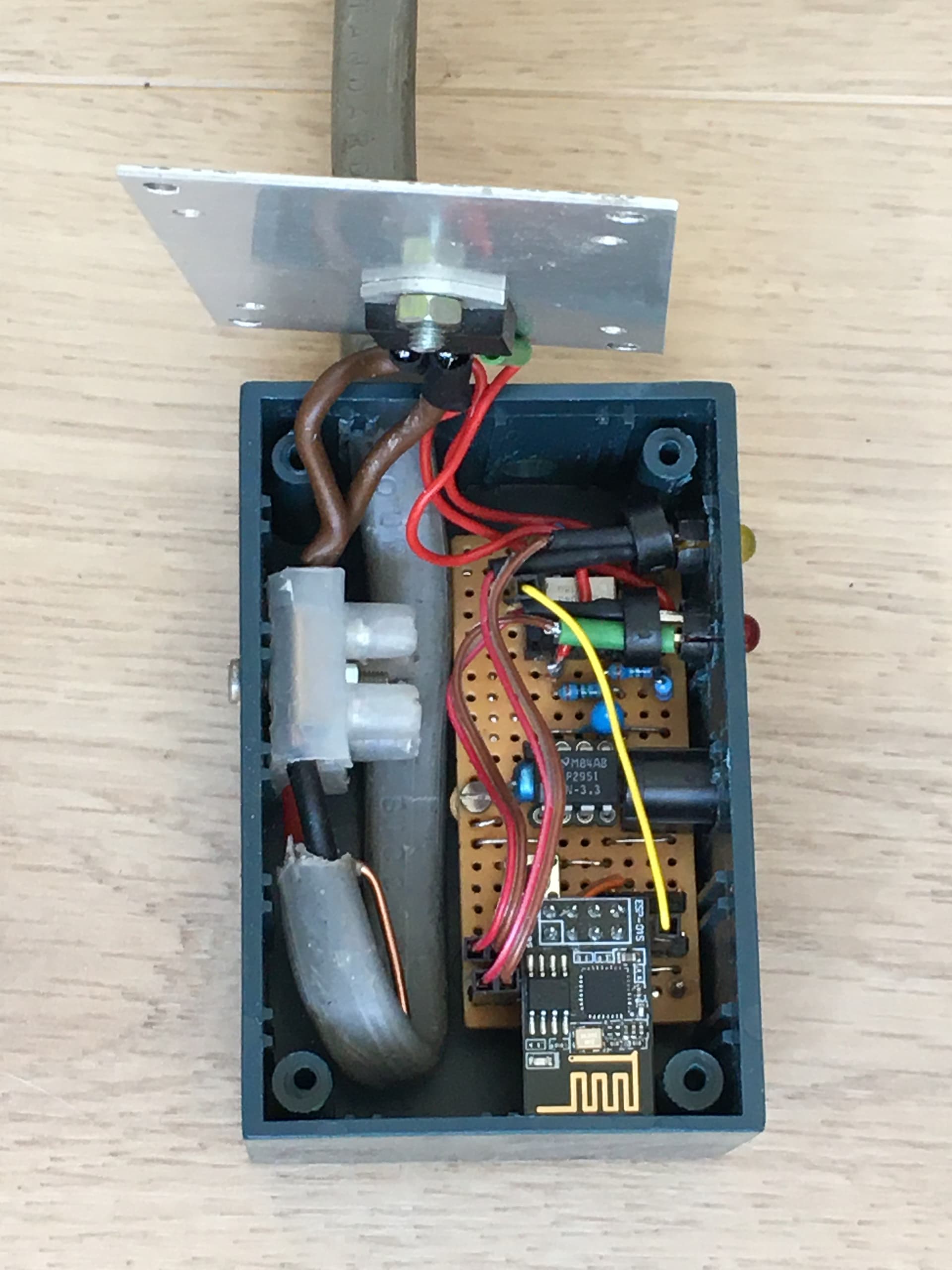
I’m not too impressed by the absence of an earth on that exposed box lid. If the triac’s insulation breaks down, the lid will become live to mains. That’s not a good idea. I wouldn’t like to have to tell the coroner “I told him so.”
And while I’m at it, those red and black cores should be sleeved or taped in brown, because both are live to line; and the cable itself is not secured to the box by a gland - this also applies to the control box - a knot in the cable isn’t good enough, it allows the cable to twist, it should also have a gland or other means of securing it.
I’m also unimpressed by the size of your “heatsink”. Have you calculated the loss in the triac with your 3.5 kW load, and estimated the temperature rise? Take a look at the triac’s data sheet and Free Flat Plate Heat Sink Calculator.