Hi, I hope you don’t mind me taping into what appears to be a great resource of hand-ons experts. I discovered this site as I’m about to build a loft monitoring system using DHT22’s linked to a Raspberry Pi to monitor humidity (I have a condensation problem due to installing extra insulation) and to turn on extraction fans. Looking to use Node.js and possibly Node.Red. Anyway, my other challenge is concerning my smart meter and my solar PV system.
Some years back I installed a SolarLog 200 to monitor my PV system and it works fine. I then asked my electricity supplier to install a smart meter with an S0 output as the SolarLog has an S0 input so I can monitor consumption alongside generation and export. My electricity supplier offered me a limited range of smart meter and I choose the EDMI Mk7C as it has S0 output.
After many months of negotiation the engineer arrived and fitted the smart meter and took a cable from the S0 output terminals into a junction box. When he had left I connected the SolarLog to the junction box using 2 wires of a CAT5 or 6 cable of length 3.5m. Both units are configured for 1000 pulses per kWh. But the SolarLog is not registering any pulses on the web dashboard.
After further numerous emails with all 4 suppliers (smart meter, solarlog, supplier and distributor) eventually another engineer makes a visit and after spending over an hour on the phone declares that there is nothing wrong with the smart meter and it is configured for S0 consumption output. He then says that the smart meter does not produce a S0 electrical pulse but merely closes a relay. He says all smart meters do this for safety reasons.
Has anyone managed to link a smartmeter S0 output via cable to a SolarLog or similar? Suggestions welcome as I seem to have met a brick wall with all parties. Why did I think this would be plug and play!
Sorry for such a long post. Hope I’ve posted in the correct section but a search on S0 showed other posts were in Hardware.
I’ll leave it to others to advise you about NodeRed and Node.js
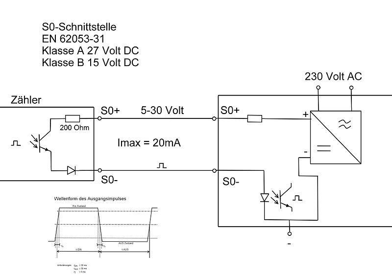
My understanding of S0 is that the sender (in your case the Smart Meter) does indeed have something that looks like a “volt-free” relay contact. It may be a physical relay, but more likely it is a transistor of some sort, probably the receiver of an opto-coupler. The normal operating voltage range will be up to 24 V d.c. It might well be polarity-sensitive.
The receiver (your SolarLog) will have the voltage source and some means of detecting (and limiting) the current that flows when the remote switch “closes”. That connection too is most likely to be polarity-sensitive.
So my best guess, if both items are playing by the rules as I understand them, is either the wires are crossed, or one or both is faulty.
Many thanks Robert for a very quick reply and the diagram.
When the engineer last called I was hoping he would have test equipment to test for a pulse but he was badly briefed and had nothing on him. I offered him a pulse detector/generator (which I’m not 100% sure how to safely use) but he declined. I did say to the engineer I thought it was more likely a solid state relay, given the high number of pulses, possibly 2 a second, but he dismissed that!
Previously I had put a voltmeter across the SolarLog S0 terminals but it just registered a few mV which I presumed was noise.
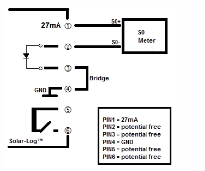
Looking at the diagram I just received from Solar Log (the one I posted) I see there is a diode between pins 2 and 3 which means I think I can safely swap the 2 wires round. Next step would be to test for continuity in the cable. This will have to wait until tomorrow when it is light outside.
I’ll get back to you with my findings. Thanks again.
As a matter of course, I never look at diagrams that are not loaded on this site (because if they aren’t here, the thread has no value in the future). I’ve loaded it here now.
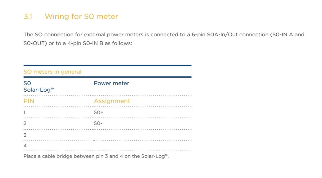
However, I think the diode between pins 2 & 3 may well be the receiving side of an opto-coupler, so connecting according to the SolarPlus diagram should work. If you have a lowish value resistor (500 - 1000 Ω) you could try dabbing it across 1 & 2 (with 3 & 4 linked) and see if it sees pulses.
Can you read a “sensible” voltage between 1 & 4 - I’d expect 24 V d.c. - with nothing connected, and 27 mA short-circuited.
If you connect an ordinary LED, a resistor (about 1 kΩ) and a 9 V battery to your Smartmeter output (like the Wikipedia diagram, +9 V = S0+, LED to - 9 V), can you see flashes?
It sounds as if your contact wasn’t sure of the standard, or maybe their input isn’t fully compliant. The 200 Ω shown on the Wikipedia diagram is presumably there to protect the sending device, and the unmarked one in the receiving device is the current limit.
[quote=“Alan_uk, post:1, topic:2188”]I suggested that I could provide a battery and resistor, or an optical coupler circuit, to provide some juice between the devices but they said no to this.
[/quote]
That should not be necessary, which is probably the reason they said no.
Quick initial reply to say thank you for putting the diagram in the post (agreed much better - I’ve now spotted the upload icon) and for your comments. I will experiment tomorrow.
This diagram from SolarLog is, they say, a recent update to their manual. Until now I’ve not got them to be clear that the SolarLog is providing the power. I had presumed (wrongly) that as the smart meter was “generating S0 pulses” then it was the providing the power. Doesn’t help that SolarLog is a German company so some potential language nuances, though their English is 1000 times better than my German!
SolarLog say they recommend and have tested Iskra smart meters and can only support that but my supplier only fits EDMI meters. But as you hint, if they all followed the standards it shouldn’t matter, but my 50 years in IT has taught me Standards are not always standard!
I checked the cable from the smart meter to the Solar Log for continuity. It was OK
I connect the smart meter S0 output to an 9v battery, 1k resistor and LED. It flashed every second. So OK
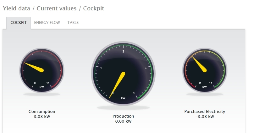
I touched a 1k resistor across the pins 1 & 2 on the Solar Log S0 plug with pins 3 & 4 bridged. (The plug was inserted but there was no connection to the smart meter). I repeatedly touched across pins 1 & 2 with the resistor every 1 or 2 seconds. I checked the solar log web display (local access http://192.168.1.11) Neither the Current Values or the Consumption screens showed any data.
I put a voltmeter across pins 1 and 4 on the Solar Log (no connection to the smart meter). There was no voltage. I was reluctant to measure mA by shorting the terminals.
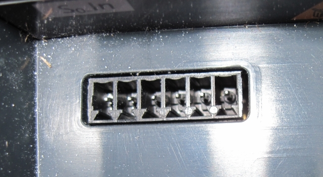
5 I have double checked the Solar Log 200 Installation manual. It gives the Solar Log plug pin connections but does not state or show the pin order. Neither is the pin order printed on the Solar Log. I’m presuming the pin order (1-6) from left to right.
Conclusion: the Smart Meter is generating pulses. Problem looks to be in the Solar Log.
I have just emailed Solar Log with the above. I’ll update this thread with their reply.
Thanks Robert for your suggestions. It gave me the confidence to experiment. I had previously been wary of damaging either the smart meter or the Solar Log.
Excellent - one variable removed from the equation.
Now the obvious question: do the Solar Log connections number the other way?
If there was no voltage, then there would of course be no current on a short-circuit.
Were you actually measuring between 6 & 3?
Check the voltage between every possible combination of pins. If you find a voltage, it ought to be pins 1 & 4, which should help you identify how the pins number.
For the Solar-Log™ 200 the S0 pin connections start from right to the left,
therefore the connections are wrong. The green connector is numbered so when
it is connected in the upper side of the Solar-Log™ is reading the pin number
1 from the right.
I’ve asked them if they could you hear me screaming all the way from the UK! I have been trying to get this working on and off for many years. I have even “accused” the electricity supplier of not installing the smart meter correctly. All because the SolarLog wiring is so ILLOGICAL.
The SolarLog has no pin markings but there is a label “S0” on the left end of the socket. So to me it was logical that the pins read left to right, 1 to 6. I even sent SolarLog a photograph of my wiring of the plug and they did not notice it was wrong!
Thank you very much indeed Robert for helping me to solve this problem.
[Actually, as far as I can remember, I’ve never been caught by that myself, but I’ve seen others suffer as you have, and I’ve also seen people caught out by reading DIP switches the wrong way - off instead of on and vice versa, which can produce exactly the same degree of confusion. It was remembering that, which triggered the suggestion that the connections were numbered the other way.]
That simple test with the battery and LED sorted that one out.
It’s nice to know I get something right once in a while. Thanks for letting me know.
You were connecting to 6 & 3 after all, then?
For the test you suggested, yes!
I have suggest to SolarLog that they change the label on the SolarLog from “S0 In” to “S0 In Pins: 6 5 4 3 2 1”
Now this is sorted I’ve been worrying about the S0 cable from the Smart Meter. I’ve noticed that it outputs right next to the network supply cable. Seems crazy to me. I would have put the connector on the other side of the meter, well away from the HV supply. So I was thinking of an opto-coupler circuit but the S0 input will need to be powered and from some rough calculations I think I would need 6Ah battery supply to run for a year. I could supply through a separate PSU so if anything went wrong then it would blow that rather than my monitoring system. What about simply putting a zener diode in the circuit from the SolarLog to the smart meter to hold back any reverse HV surge?
I don’t think any of that should be necessary. The meter manufacturers obviously think it is OK (and unless the meter is liable to get a soaking, they’re probably right) and it’s optically isolated inside the meter. I wouldn’t have given that a second thought.
I believe we can close this thread now. Thanks again Robert.
I’m now building an loft monitoring and air exhaust system. Since adding extra insulation I’ve noticed on balmy days in the winter a lot of condensation dripping from inside the loft, despite vents all round the house in the sofits. I was advised to install vents at the apex of the roof but this would be expensive. Scaffolding would cost at least £1,000 ($1,000) plus builders fees and I would be inclined to have all the ridge tiles re-cemented at the same time.
The monitoring system will be based on Raspberry Pi with 3 x DHT22 humidity and temperature sensors driving 2 x extractor fans vented to apertures in the sofits. Software to be written in Node-Red as I’m familiar with Javascript. If it’s successful I can add a write up if that is thought suitable.
