Large discrepancy between pulse counter and CT

Hi,

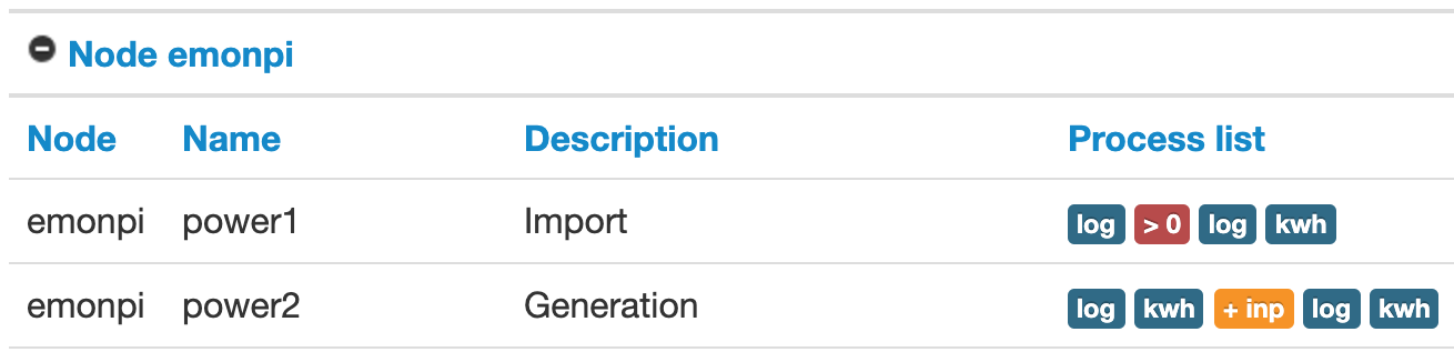
I’m just getting started (got my emonPi yesterday) with my solar PV system. I’ve got two CTs, one for import and one for generation, and set them up (hopefully) as a type 2 system:

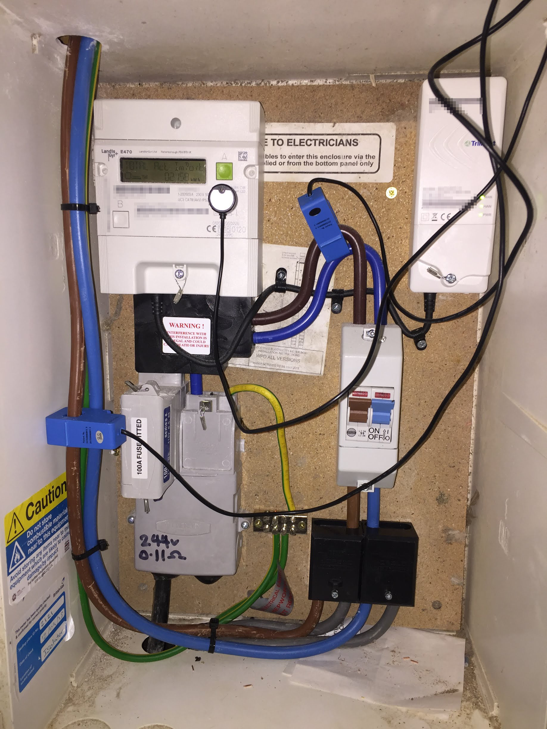
CT1 is attached to the output from the import meter (top center), and CT2 is attached to the PV input (far left, middle). I also have a pulse counter attached to the import meter.

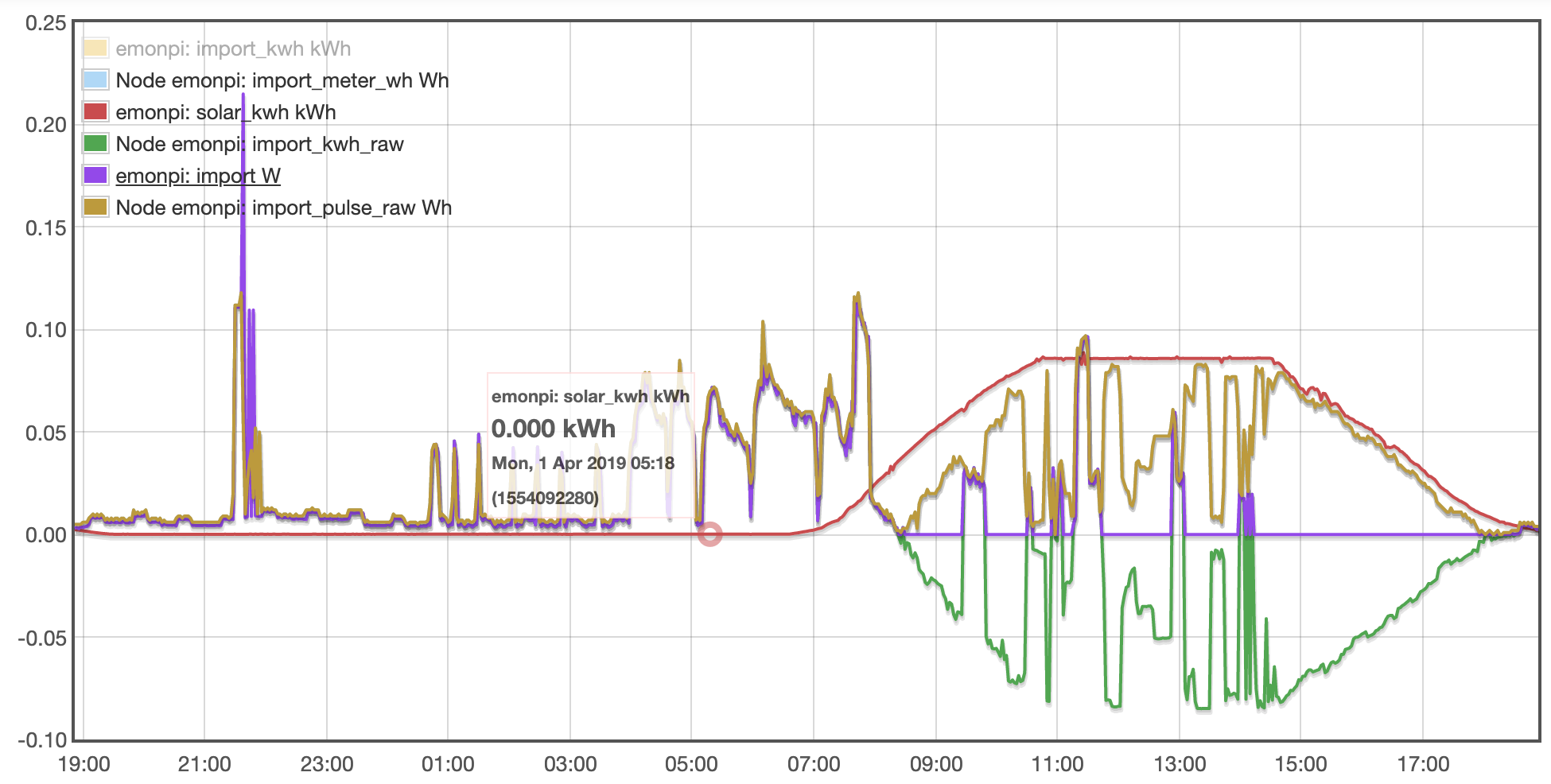
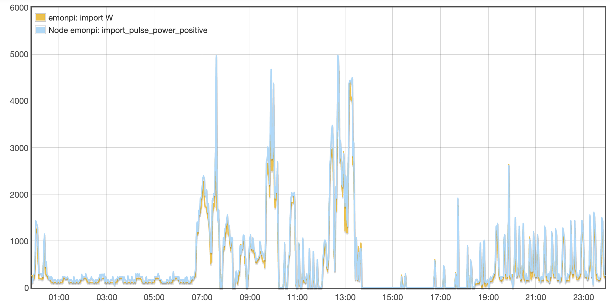
I am reading figures, but struggling to make sense of them. The import CT approximately agrees with the import pulse counter when PV generation is low, but it’s completely different (often 0) when the PV is generating (sunny daytime):

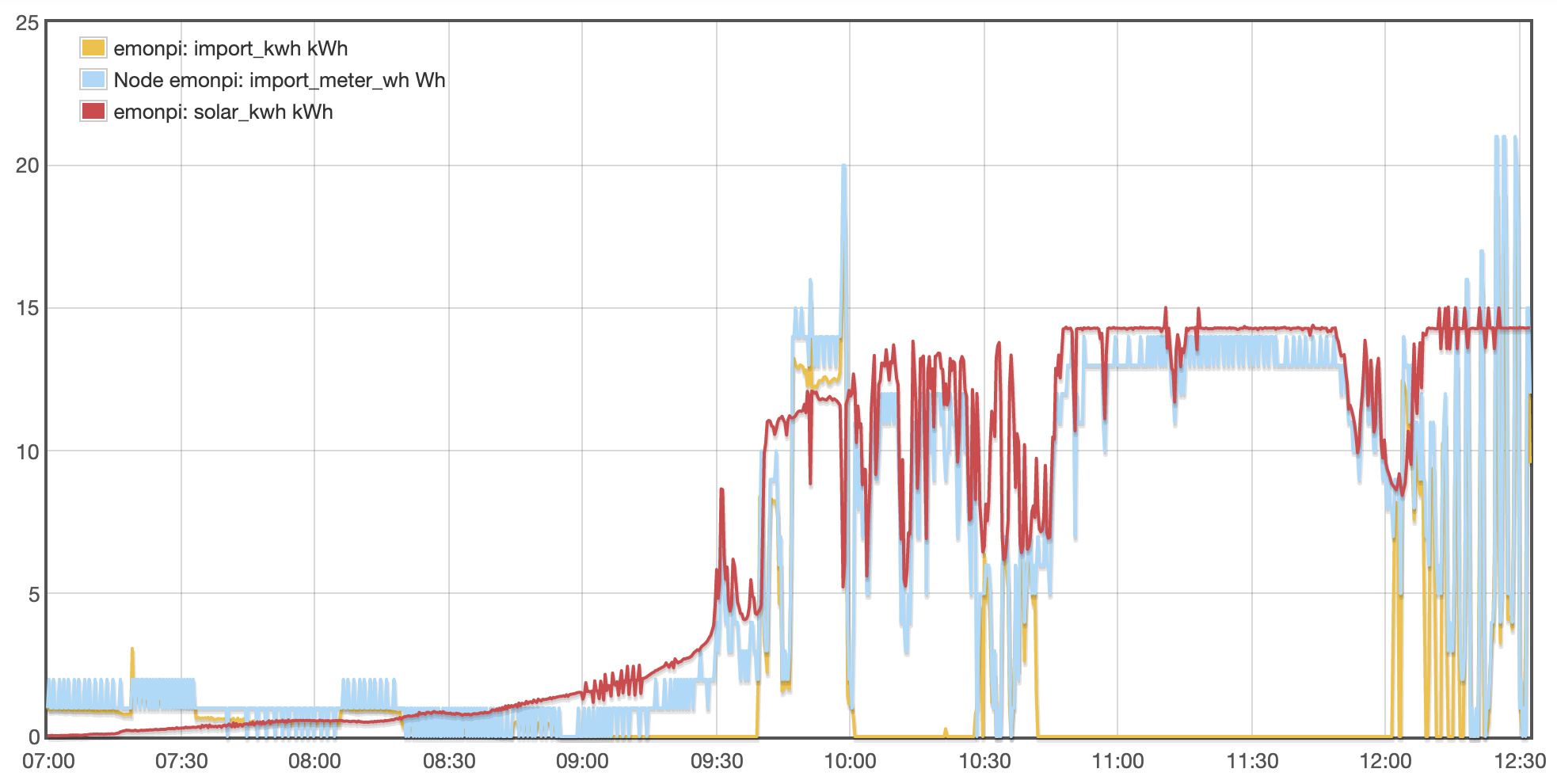
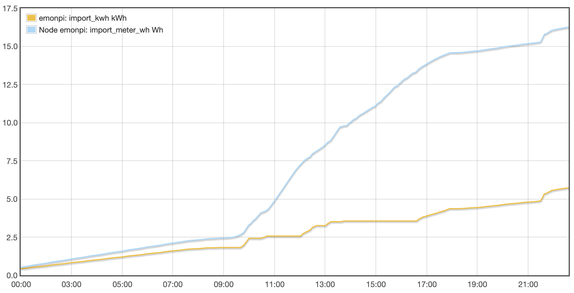
The values on this graph are delta Wh.

Between 09:40 and 10:00, the import meter approximately equals the CT, despite significant solar power being generated. Then the CT reading drops to 0 (between 10:00 and 10:30), but the meter is still pulsing!

I’m more inclined to believe the import CT, because there are long periods where it is flat (zero import) which probably correspond to net generation. But the meter is what I’m being billed for, so I want it to be correct too.

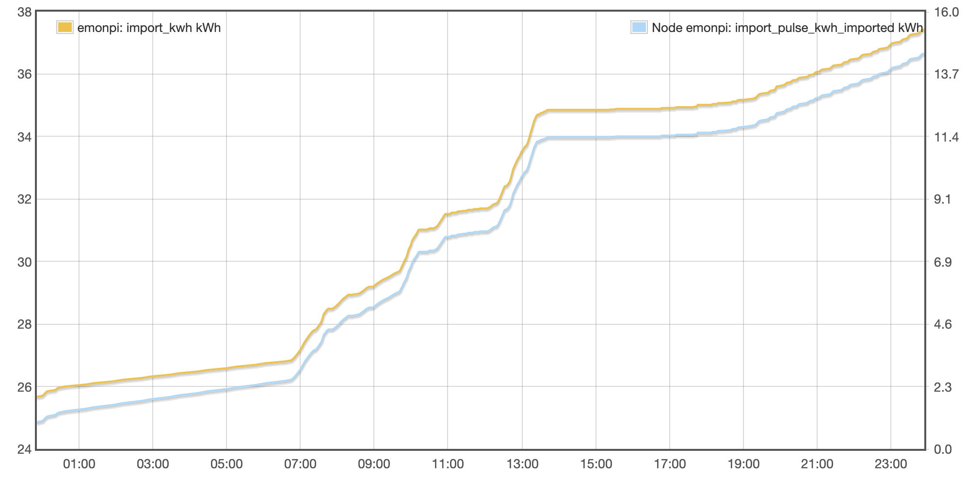
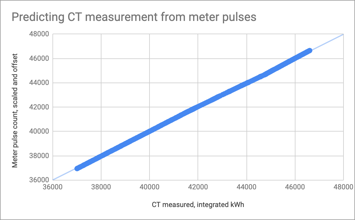
Comparing the total kWh of the two sources also shows them increasing approximately in line, except during the day when the PV is generating. For reference, my smart meter says I’ve used (imported) £0.88, which at 17.37p/kWh is 5.07 kWh. This agrees more closely with the import CT, according to which I’ve imported 5.4 kWh today:

Am I doing something wrong? Is my meter pulsing even when I’m exporting, despite it having no export reading that I can find or access?

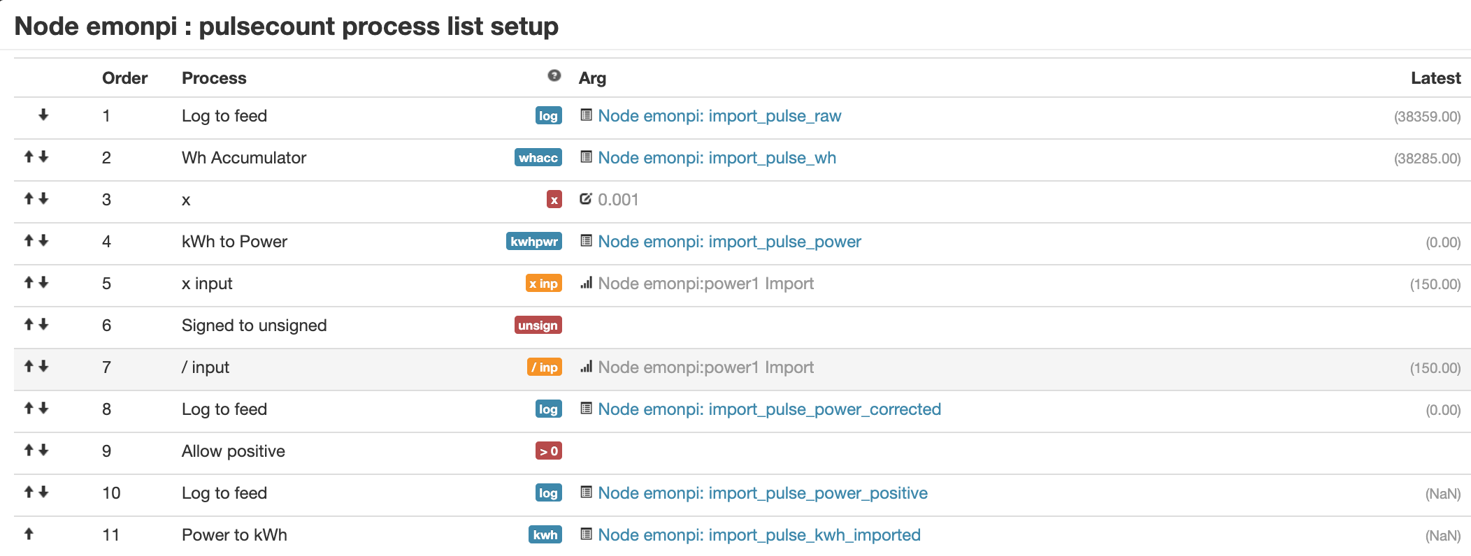
This is how I’ve set up the pulse counter input, I hope it’s correct but please do correct me if it’s not:
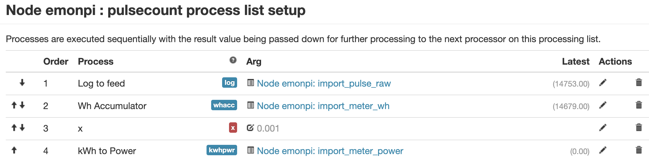
Thanks, Chris.

Do you mean the import c.t. agrees with the pulse rate when you are not generating, but the pulse count is static when you are exporting?

If so, that’s as I would expect. The optical pulses from a meter cannot indicate the direction of energy flow, so most meters show a steady red LED or nothing when you are exporting. Yours might be different, and could pulse on exporting, and it does indeed look as if that might be the case. But when that’s happening, I’d also expect the import c.t. to be registering a negative power, meaning export - assuming of course you have an a.c. adapter fitted and in use. (Did you notice whether it recognised the a.c. adapter at power-up, does the emonPi’s LCD show a varying voltage, or a constant rock-solid “230 V” ?)

Is that meter box normally in darkness?

Do you have PV diverter? If you don’t, I’d expect a negative slope when you’re exporting (unless of course you’ve blocked that in the emonCMS processing). If you do, then the flat line indicates the diverter is doing its job correctly.

It might help to set up a dashboard showing power - import, generation and house consumption (that being the difference of course).

Hi Robert, thanks for replying so quickly!

Do you mean the import c.t. agrees with the pulse rate when you are not generating, but the pulse count is static when you are exporting?

I think that the import CT appears to agree with the pulse rate when not generating, and sometimes randomly when generating, but at other times (when generating) the import CT shows no import, but the pulse counter is still recording pulses!

I do have an AC adaptor connected, it is working, and the meter box is fairly dark (not 100% because it doesn’t close properly with the emonPi cables jammed in the door!). I don’t have a diverter. I have the My Solar dashboard set up and, since it uses the CTs and not the pulse counter, it seems to make sense. But I’d like to double-check the CT readings using the pulse counter.

most meters show a steady red LED or nothing when you are exporting

If the red LED was flashing on and off, that might explain it, but it looks to me as though the meter is pulsing for export too. Unfortunately I can’t find a manual for the meter (Landis+Gyr E470) online to check whether it’s supposed to.

The CT measures zero when exporting because I applied the default settings for a Solar PV system, which include filtering out values < 0, to prepare the import CT sensor readings for the My Solar app:

I’ve since created a raw feed that doesn’t do this filtering, and we can see that when the import power is greater than 0 (net importing) then the instantaneous power derived from the pulse counter matches it very closely, and when the import power is less than 0, the pulse counter power shows the exact opposite:

I take it that this is very unusual and not supposed to happen? I can see that some meters have a mode called “Import meter with Power Flow Insensitive enabled - The LED pulses for forward and reverse energy”. Perhaps this meter does too?

I’m going to try to setup a feed for the pulse counter that inverts when exporting, to see if that makes it align correctly with the CT, as I suspect it will.

That answers your quandary, I think.

There really isn’t a way of knowing how a digital meter will perform. It’s our belief that apparently identical meters (i.e. the same manufacturer and model) can be and are programmed differently according to the customer’s (i.e. the electricity company’s) requirements, so even though they eventually measure the same quantity, there can be small differences - such as how the LED behaves.

This is a reason why we rarely suggest the pulse counter as the primary measurement - although by definition it is 100% accurate while importing, it’s anybody’s guess what happens when you begin to export. At best, and usually - in our experience, there’s no pulse output. But in your case, it appears that it emits pulses just the same.

1 Like

It is as comman one way as the other. I have seen several meters that pulse for both directions. It is after all, just a visual confirmation usually. The registers are usually progamable and set by the supllier. You can get all configurations, some meters sum the flow of both directions, some subtract one from the other to get net, even that is possible as either fwd minus rev or rev minus fwd.

What might be quicker and easier is to just set up a virtual feed that sums the import and export feeds (assuming you are recording both) this will use the data you’ve already collected and should match the pulsecount derived feed. If it does match, you can explore making the directional pulse based feeds. If it doesn’t match, then either the extra pulses are erroneous (stray light etc) or they are not directly compatible due to the switching of direction, either way, if you determine the pulses are not matching up, it saves you the effort of creating the directional feeds and waiting to see how it pans out.

I tried creating virtual feeds, but despite the contortions I had to go through to create them at all, I was not able to graph them, so I don’t find them very useful.

In case it helps anyone else, I managed to create a filtered pulse feed with the following input processing:

Explanation of the steps:

  • Log the raw pulse count (for debugging, recommended)
  • Log the accumulated pulse count (maybe not useful now that we know that the meter pulses both ways, as the import and export payment rates are different)
  • Convert to kWh, then to current power (unsigned, so also not very useful)
  • Multiply by import CT input, to get the sign
  • Signed to unsigned (abs)
  • Divide by import CT input, to remove the quantity again, leaving only the sign
  • Log to a corrected import/export power feed (this one goes positive and negative, so is more useful)
  • Only allow positive values (leaves only imported power)
  • Log imported power
  • Convert to kWh and log (imported energy in kWh)

I wish there was a “copy sign from input” or some “conditional on input” nodes, which would have made this much easier.

The last two logged feeds (imported power and energy) agree quite closely (to about 10%) with the values measured by the CT input. I’m inclined to put more faith in these as they come from the meter. Despite all the transformations, we only rely on the sign of the CT input, not its magnitude.

The import meter registers 13.5 kWh in 24 hours (excluding pulses when the CT input was negative), while the CT registers 11.7 kWh.

They have peaks at the same times (in sync), not disagreeing except perhaps in magnitude (a little hard to tell from this graph, unfortunately).

From your graph, and looking only at the difference between them so ignoring the offset, they look a lot closer than 10% to me, more like 1%. And you can’t complain at that, especially if you haven’t yet calibrated the emonPi. Statistically, most emonPi’s should be much closer than 10%. You can always make a very small adjustment to the "scales = " multiplier in emonHub to get the correlation closer.

@TrystanLea should see this, so he might consider your request to extract the sign of the current/power so that you can use it to determine the “sign” to apply to the pulse count, or indeed whether to ignore it one way.

I’m glad you got it sorted, but I’m not sure why you had issues with the virtual feed, I simply suggested using one virtual feed to add 2 real feeds, that should have been very straight forward. I have, however noticed someone else is having an issue in another thread so maybe there is a bug?

Now that you’ve got import-only readings from the pulse count readings, you should be able to compare these against the actual meter readings from the meter’s display. In a perfect world, they should match exactly :slight_smile:

I have a meter that works the same way as yours, so I may try to replicate your setup.

Unfortunately I do not have an export meter, so I don’t think I can do this. I can measure export using the CT attached to the grid (meter) connection, but not necessarily accurately.

I have used a linear regression to estimate the constant of proportionality (beta) between the import meter pulses (having done my best to filter out export pulses) and the grid CT reading. I get a very good relationship between predicted and actual CT readings (Pearson correlation coefficient of 0.99988), with a beta of 0.872, which suggests to me that the CT is under-measuring the current by 14.7%.

I haven’t calibrated either CT specifically, but the extent of the agreement makes me think that this is a pretty accurate calibration in itself, so I can apply this scaling factor to the grid CT’s feed. I will probably now move the pulse sensor to the generation meter, and use it to calibrate the generation CT.

I’ve had a quick look at your spreadsheet, and it looks as if most of the time you’re measuring significantly less than 1 kW. It might be worth pointing out that the c.t. itself is only specified for current (amplitude) accuracy above 10% of rated current (that’s about 2.4 kW) and that the power error is the combined error of both voltage and current transformers, their respective input circuits and the ADC itself. My feeling is that most of that error will be due to the phase error in the c.t., which increases rapidly at low currents and isn’t specified by the manufacturer. Unfortunately, there’s no practical way to compensate for the phase errors in the emonPi.