We are just over 1 year into having a Vaillant Arotherm+ 7kW heat pump. Overall it is working well but I am slightly disappointed with my space heating SCoP - currently sitting at ~3.6. I had hoped it would be 4.0 or more. We have also been using the heat pump for cooling - which achieves a high COP in summer - and raises our headline average to ~3.7.
I suspect that the main problem is that we had underfloor heating installed throughout the ground floor, as part of a major renovation but it was done before I knew much about heat pumps. It is very well insulated under the screed but was done with 200mm pipe centres - requiring a higher flow temperature.
Would anyone be willing to take a look and see if there’s anything else obviously off in my data?
Two contributors in my opinion: First, a design temperature of 45°C at -1.7°C is quite high for UFH. From your data, it appears the actual flow temperature at design temp is lower though. Secondly, and probably more impactful are the defrosts. Look for example at Dec 5th, you are constantly defrosting and it appears the heatpump struggles to keep the house warm. This eats huge amounts of energy. Even at 5°C outside you’re sometimes getting almost half-hourly defrost cycles (e.g. Dec 20).
With all this in mind your SCOP appears quite good actually!
Yes, I have tried to drop the value on the Vaillant weather compensation curve - I currently have it set to “0.50”. So the flow temperature doesn’t often reach 45°C.
What can I do to try and reduce the number of defrosts? The heat pump is in front of a south-facing wall but in winter it is in the shadow of our neighbour’s house all day.
And probably not much that can be done to reduce humidity?
I fear there’s not much you can do. Temperature and humidity are the main culprits and if you’re in a wet climate, you’ll have these issues if temperatures hover around zero. This is in fact so bad that a heat pump’s power output is up to 20% below quoted nominal output by the manufacturer, at least for Vaillant units. Have a look here for example: Vaillant maximum output capacity testing
You mention UFH on the ground floor only and a mix of both new and old radiators upstairs. I think your radiators are setting your heat pump flow temperature. The radiator water temperature is then typically blended down for UFH operation. I assume you have a blending bypass valve arrangement to reduce the hot water temperature to the UFH. A 45C MWT with a 200mm pitch would generate a heat output of 121 W/m2. That’s a lot of heat into a room. If it was operating with a MWT of 35C, then it generates 84 W/m2. That’s still a decent amount of heat into a room. The 200mm pitch may not be the issue.
Your upstairs radiators will most likely have set the design choice for the MWT =45C. This should be part of your heat loss calculations for each room. As you know, the radiator heat output is dramatically affected by lowering your MWT. At 45C you have 40% of the radiator output against the typical rating, but at 35C it is 21%.
If you could lower your MWT of 45C at your -1.7C design case, then your COP should improve. You can get a fair idea from the valiant heat curves, but you are already operating near the 0.5 curve and a water flow temp of ~39C. The challenge is whether you can still lower the heat curve value, but still warm the upstairs and downstairs rooms. If this is possible, then your COP would increase.
My question is when you attempt to drop the heat curve further, is it the upstairs or downstairs rooms struggling to get to the room temperature, or both?
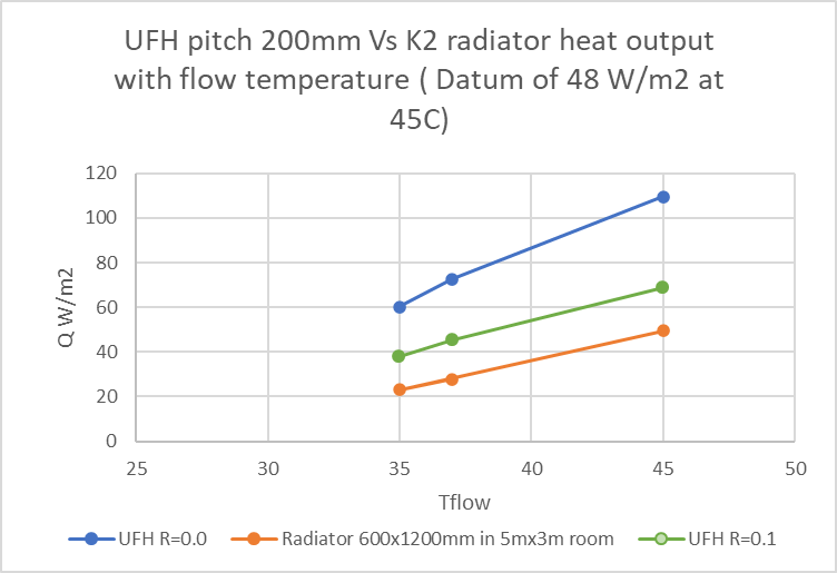
I hope the plot here helps. It shows the heat delivered by the UFH with a pitch of 200mm against a K2 type radiator. The radiator size is chosen to deliver 48 W/m2 at your original design case for an notional room size with a flow temp of 45C. The 48 W/m2 was based on your 6.5kW ASHP in a 136m2 house. (6500/136=48 W/m2). It suggests the UFH with 200mm pitch may not be the constraint. The UFH (200mm pitch) should typically offer higher performance than a radiator system. Unless it has a larger than normal room floor area unheated, or a carpet, or wood laminate covering with a TOG>1.0. If you have an UFH mixing valve, then that could adversely affect the UFH flow temperature. It was difficult for me to understand the heavily insulated piping around the UFH manifold.
Hi Judith, I will be able to re-check the CIBSE guide in a few weeks. However, from memory, the R=0.0 is correct and applies to ceramic tiled floors with no thermal resistance. The ceramic tile allows more heat into the room. The R=0.1 is probably a carpet (ToG=1.0). We opted for wood effect ceramic tiles in our house and small rugs for this reason.
The flow temp spikes about 4 times/day, presumably heating of the cylinder? If so, you could try changing the hysteresis value to reduce the number of DHW runs.
Thank you very much for your replies. I have been giving it all some consideration.
At the moment, it feels like it is the downstairs is struggling to reach room temperature. But I think I need to measure it to verify this. Sitting still / moving around makes such a difference to how warm you feel!
Our underfloor heating manifold is part of the primary heating loop - we don’t have a blending valve. However, my installer did put in an emergency shut-off valve, in case the hot water diverter breaks, which would result in too much heat going through the UFH.
It was -1°C outside this morning, and the flow temperature was 39°C. We have an engineered wooden floor (R=0.15?) and the surface temperature is currently ~24°C.
The screed is unintentionally really thick, which is great as a thermal store, but there is a big lag. This was very noticeable when we previously had a gas boiler (and a blending valve at the time).
Thinking about the number of defrost cycles, the heat pump is installed in an alleyway at the side of our house. There is 260mm of clearance behind it, a wooden fence 800mm to the right of it, 1630mm to the neighbour’s wall in front, and it is unrestricted to the left. I guess one solution would be to rotate it 90°, so it is pointing down the alleyway - but not ideal for access / aesthetics!
The hot water situation is caused by us using a lot of hot water but not having a big enough hot water tank (180L was the size recommended to us by Mixergy ). It is scheduled to heat to 100% twice a day, but it ends up doing additional runs as well. I have it set up to heat to 55°C at night (with cheap electricity) and 42°C during the day. So I am deliberately reducing my DHW COP with an aim to save money.
The things I am planning to look into this year are:
Temperature sensors around the house, to get data on which rooms are struggling
See if there is micro-climating around the heat pump and if anything can be done about it
Get a second electricity meter for my Mixergy hot water tank electrical circuit (which includes pumps), so I can get to H4.
The physical location and layout of your heat pump looks fine to me. I have a similar layout and it’s all good. The location of the heat pump is not be an issue in my opinion. No need to rotate the heat pump.
I guess the engineered wood is 16mm or 20mm thick? It will act as greater thermal barrier when thicker. It’s a common conversation in most households of function versus form.
The thicker screed should not be an issue when operating 24/7, especially when it’s already up at temperature. As you say, it’s a good thermal store.
Try obtaining some information on the flow valve settings ( litre/min) on each floor loop for the UFH manifold versus the original heat demand per room whilst you are in the winter season. This is the ideal time. You should then get a better idea of the heat supplied upstairs (rads) and downstairs (UFH). You said it feels like downstairs is colder, but you hint that it may not be all of the downstairs rooms. You’re right to take some measurements. I spent a few hours adjusting these flow valves on a cold day to calibrate the flow to each room. Eg Opening the manifold loop flow valve for the living room and then restricting the flow to the warmer utility room, etc. in my case, I do need to do some balancing of the rooms to achieve the same overall flow rate, otherwise I reduce the flow supply upstairs. The plumber may have used a “rough” setting per loop when commissioning the UFH system. A handful of small low cost digital thermometers in each room gives a reasonable measurement to call for more or less heat per room. In my house it’s my wife that is the final arbitrator and not the digital thermometer. Comfort is king!
Hi njh, Here is the UFH lamiate floor versus radiator comparison more tailored to your situation. The data was taken from the CIBSE guide book. It suggests a 22mm wooden laminate floor cover with R=0.15 should still perform better than a K2 radiator. I added the 150mm pitch option to show the extra heat output compared with the 200mm pitch. It is ~3 W/m2, which is pretty small. So the choice of a 200mm pitch or a 150mm pitch does not appear to be a deciding factor for your UFH system heat output.
You may want to gather more information on the flow and heat balance in to the ground floor UFH heating loops and the upstairs radiators. The very “simple” chart suggest the radiator heat output still constrains the flow temperature compared to UFH, but it all depends on your house characteristics ( radiator sizes, etc, etc).
It depends on the household, the room use ( study or bedrooms) and room winter characteristics ( big or small south or north facing windows).
That’s the “comfort” level for each individual and family. Most families find it by trial and error. It may indeed be the case njh prefers cooler rooms upstairs ( say 18C instead of 20C ) and the radiators upstairs are actually not a constraint. It is difficult to offer more sensible advice without room heat loss information.
The chart assumptions are very simple. However, it highlights an area of attention often set coarsely by installers when balancing rads upstairs and UFH downstairs in the good weather installation season. In my opinion, it’s a task that is best performed on cold days with some knowledge of room temperatures.
As a general note - for other data gathering, Home Assistant (HA) is the way forward. It will connect lots of disparate cheap sensors and you can then send the data to emoncms.
Yeah I just have a pile of Zigbee temp/humidity sensors from aliexpress, they cost £2.50 each and function perfectly now that I’ve extended the mesh network (using cheap smart plugs off aliexpress).