Very nice, Bob!
This is what OEM should aspire to be.
Very nice, Bob!
This is what OEM should aspire to be.
Look very very good!
One thing i could not find: does it support 3 phase measurement with only 1 VT? (i read that 3phase and 3VT work)
The only way I know to accurately measure three phase power is to treat
each leg as an independent load and add the three together. That said,
you can probably get pretty close by making assumptions about voltage of
two legs relative to a third measured leg. I think one of the eMon
boxes does that, and its probably reasonably close for applications
where the legs are loaded symmetrically. I wouldn’t count on it to
measure individual circuits in a three phase panel where the legs are
loaded differently.
But to answer your question more directly, no, there is no software to
perform the necessary phase shifts to estimate three phase power based
off one VT. IoTaWatt makes it easy to connect three VTs.
Wow, very inspiring, great job Bob!
Looks really impressive. Got a few questions:
Here in the UK there are a couple of suppliers that offer the adafruit Huzzah and datalogger so that’s good.
Any progress on production options? I could do with 16 ADC boards…
When you specify more than one VT, a voltage reference specification appears in the CT input edit dialogue. Was in the old app, dropped out in the remake, is in my current version. Was always in the code.
Its all about the log file. Currently whites 256bytes every 5 seconds. That’s about 1.6GB per year. My current design will probably use half that. So depends…
You should ask Mr. Wall for a lesson in burden/turns/current, or read his excellent tutorials in the learning section. The reason I added 1.2V in the adafruit feather design was that I have some revenue grade .33mv CTs that I came across on eBay for short money. Truth be told, with the 12bit ADCs, even those work fine at 3.3V. I have abandoned 1.2V in my latest design. I have an HCWT-004 monitoring a solar inverter at one installation. 3.3v 24ohm burden. The thing has been within 0.1Kwh of the (Solar-Edge) inverter web monitor application, which is revenue grade because it is used as a basis for SREC (Solar Renewable Energy Credit) payments. Not bad for a $1.98 CT.
I see a potential problem in that one side of the VT goes to ground through a 10uf capacitor. If the polarity is reversed between the two IoTaWatt devices, and any elements of the DC circuitry are connected (like the ring of any 3.5 mm stereo jack), you will have a short of the 9VAC, potentially through the DC circuits of one or both units. So the answer is it can be done but has to be done with strict observance of polarity.
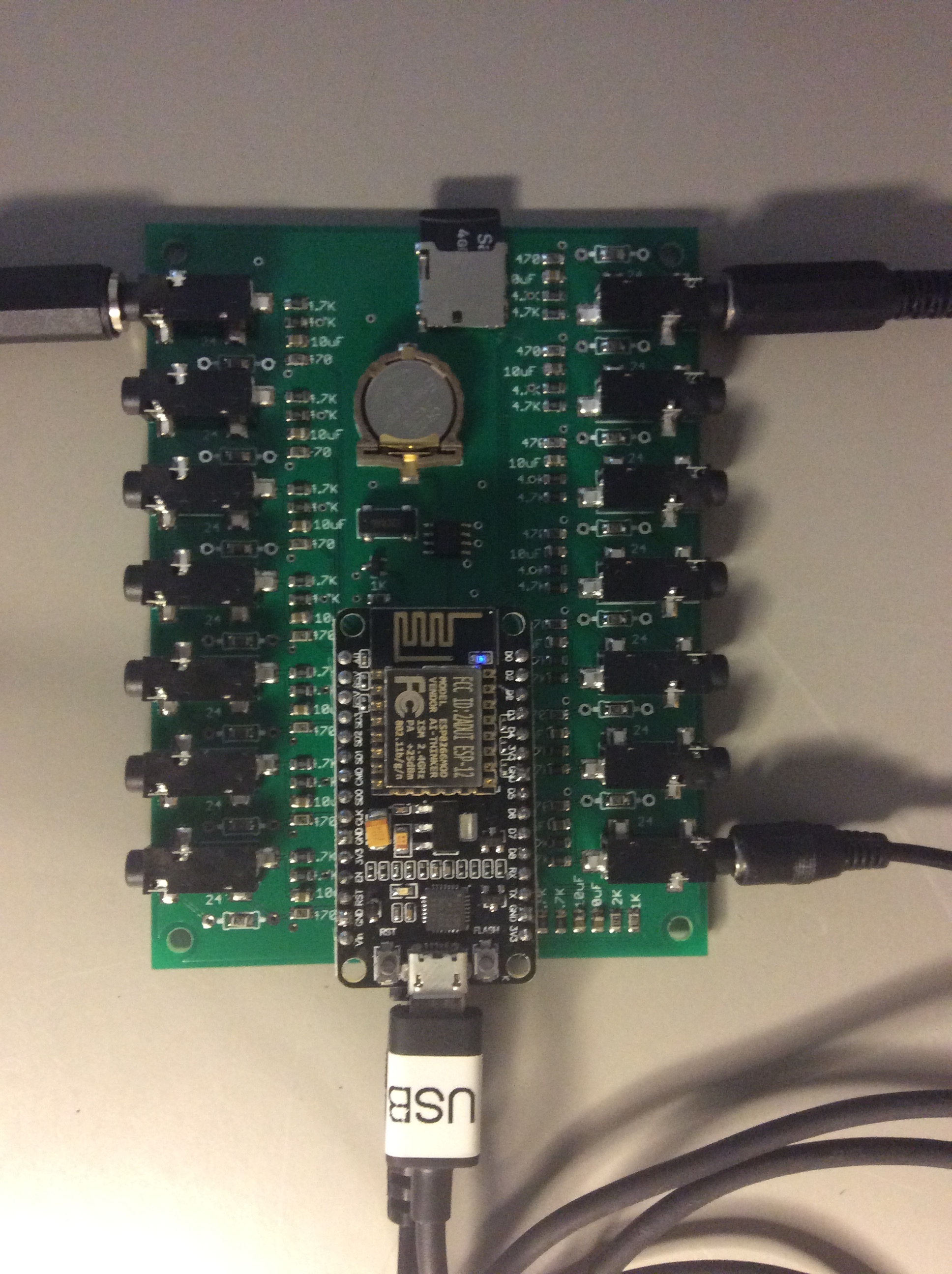
I had gone with the Adafruit components in the hope that I could convince Adafruit to build an ADC boads to round out the hardware and make it available to people. They don’t even answer emails, and their stuff is relatively expensive, especially with their shipping. So I have given up on them and gone back to the $5 (free shipping) nodeMCUs which work fine. I have put the RTC and SD on a board with two ADCs for a 14 channel + VT 3.3v design that is working great - all SMD except for the nodeMCU.
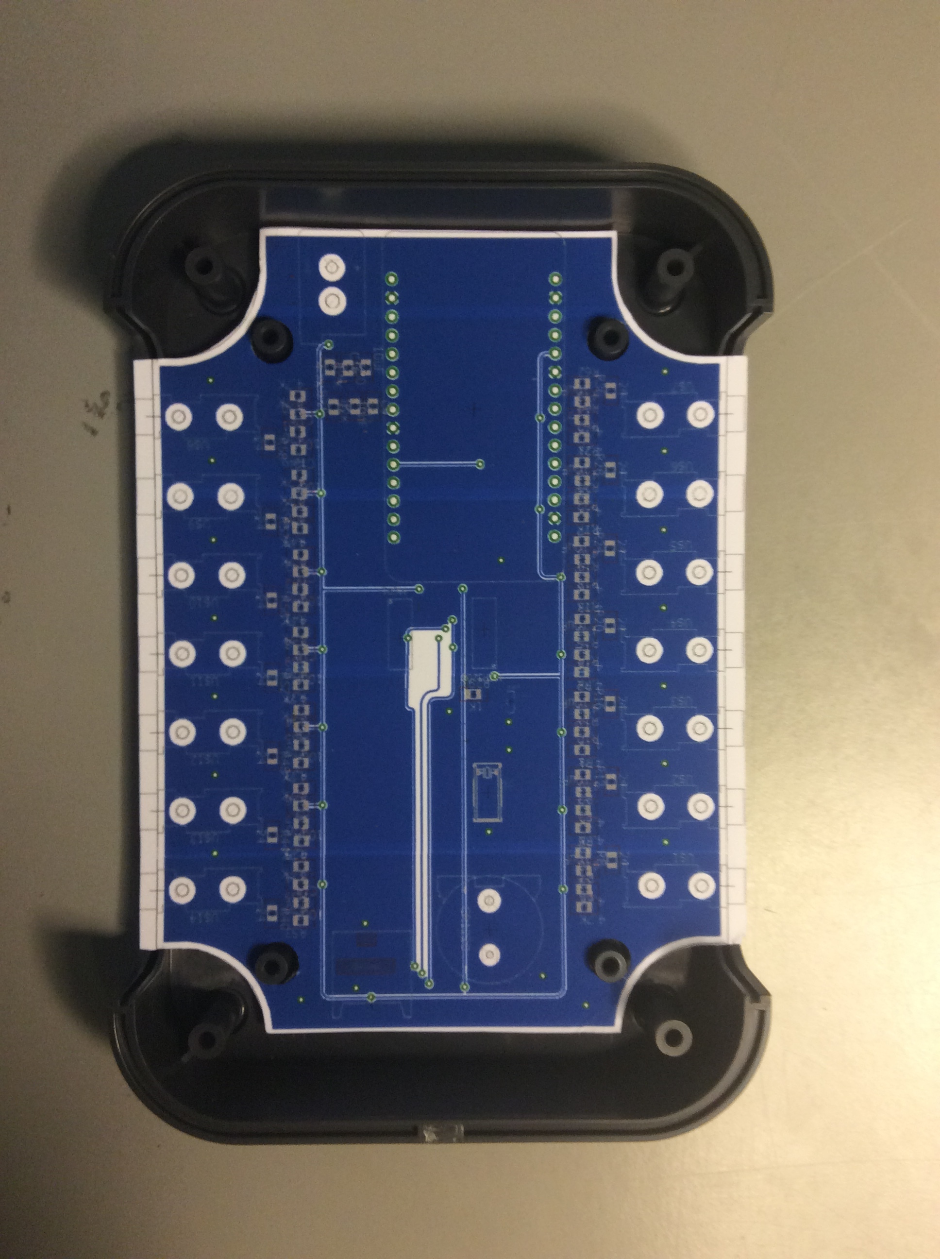
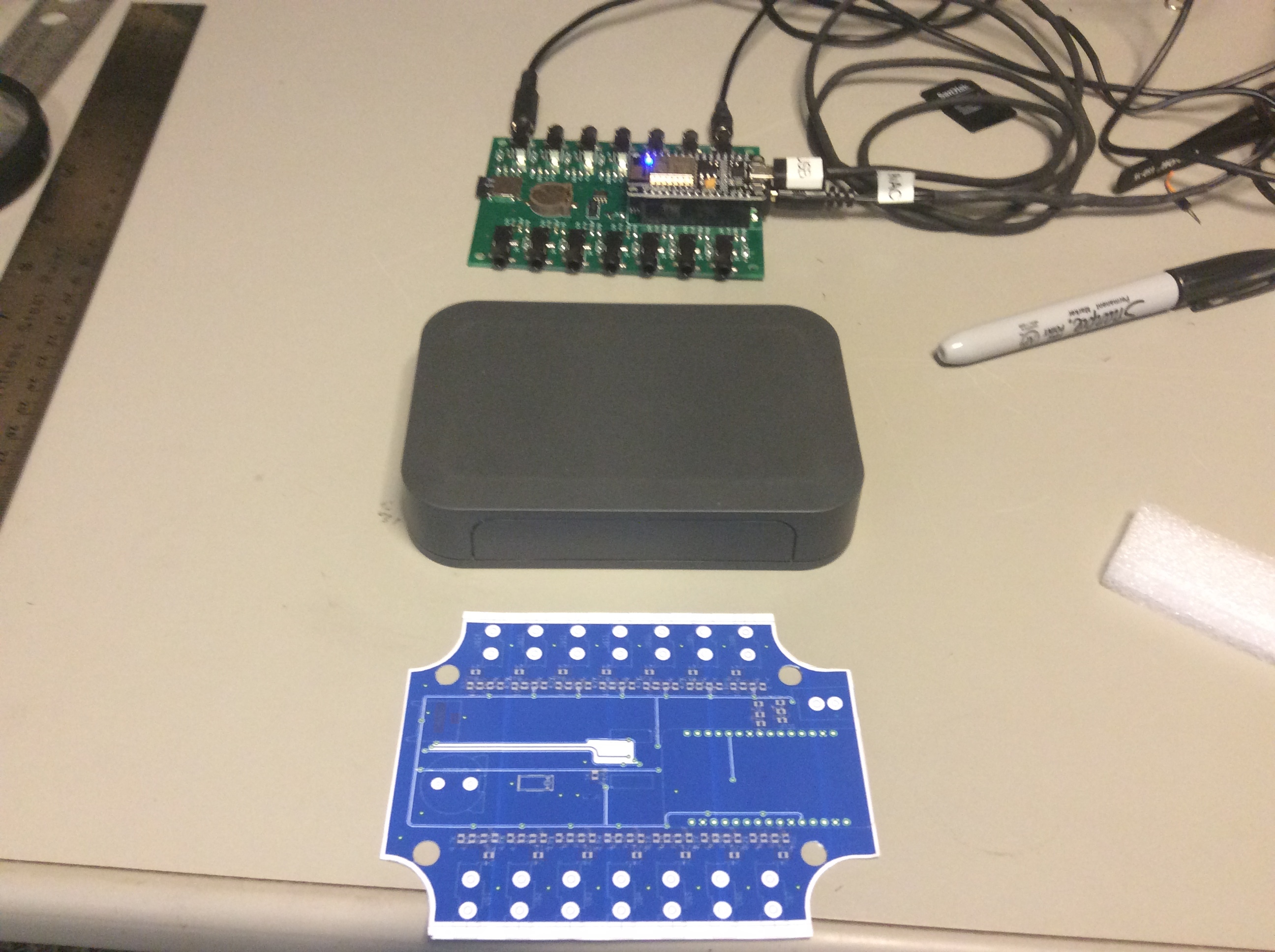
The final board went to PCBway today, should be back in a week. I have sourced an enclosure, have samples, and am waiting for a quote on machining the openings. I have an excellent local assembly company that is quoting board production. So I will need to decide soon if I go to market with it.
Not really sure what you are doing. I get the sense that you may be associated with the OEM people. Last I heard from Trystan Lea, he played with the device I sent him for half a day, left it connected as voltmeter for a few weeks, then it went off the air. Not a word from these folks, so I am considering that overture as dead as the Adafruit effort.
Not associated, I’m a long-time user of the OEM stuff and have contributed some code in the past. I write software and integrate systems, particularly for smart home/energy applications. I’ve got a big project at the moment that requires me to monitor just over 50 circuits in different parts of a building, some of which are three-phase. Hence my interest in your board, as I don’t see anything else available that supports a sensible number of circuits and can use an existing radio infrastructure (ie. site-wide WiFi).
Sounds like I need to wait a bit longer… do let me know when you are think you may be in a position to go to production.
Matthew
I’ll let you know. Now I seem to recall that you said you from down-under. I should have some boxes in a month or two at the most. If you want some boards, I buy these prototype boards in batches of ten and typically use only a few. You can have a few for shipping if you are inclined to populate them.
If you want to do something complementary to this effort, take a look at Amazon Web Services with an eye toward using it as a web data repository for IoTaWatt. All it really needs is a flat file, and the size of it is trivial by AWS standards. The IoTaWatt does the heavy lifting and a JS routine can implement the output channel scripts in a front end to any app. Would be fast and cheap.
I’ll be going there when I finish this hardware sprint.
I updated the online version with the development version that allows you to select from the available VT when there are more than one.
There is also support in the program to allow correction to virtually any phaseshift, so with a single VT, you might get satisfactory results by adding 120 or 240 to the phaselead on the other legs. This is similar in principle to the way the eMon handles three-phase with a single VT, but quite a bit different in implementation. With nearly ten times the sample rate, the accuracy should be improved. I haven’t had a chance to get to a three-phase site and test it, but when the time comes, maybe you could do a comparison. Both methods can be run simultaneously on the same IoTaWatt and the results compared.
Still very interested @overeasy, just been a bit flat out with emoncms developments, which I also need to post here about, your new board design and the enclosure in particular looks really nice!
@overeasy
Hi Bob
I’m following your project with interest, I can test your hardware at a UK three phase site if needed.
Regards
Dave
Bob, I was just about to have a few boards manufactured for home use, are you planning on publishing the latest version? If so, I will wait.
Brian
Dave,
Thanks, I’ll put you on the short list for a prototype.
Brian, were you just getting the PCBs or having them built out as well? If you are looking for built-out boards, the prototypes should be available in three to four weeks.
Bob, I was looking for the PCBs, but the lead time at the place I was looking at (https://oshpark.com) would be 2 or 3 weeks I think, so I would be interested in one of the prototypes.
[quote=“overeasy, post:49, topic:2989”]
I seem to recall that you said you from down-under.[/quote]
That’s probably me and I think I am about ready to go for it too. Single phase 240V. I’d probably order a batch directly from China.
@overeasy: Exactly what did you order? I’d like to see their price on populating the SMT components too. I’d hand solder the headers and screw terminals.
[quote=“overeasy, post:47, topic:2989”]
ask Mr. Wall for a lesson in burden/turns/current …[/quote]
I’ll do that. (I thought I was on top of it a while ago but I’m confused again.)
@Robert.Wall What VT / CT s would you recommend for a range of household uses on the Iotawatt? I don’t need revenue grade but I’ll want a fair few and I’d prefer to go with solid core from China.
I have not looked at the requirements of Iotawatt. It’s relatively simple to do the calculations, as a guide I aim for 1.1 V rms output - either across the burden resistor or from a voltage transformer + resistive divider chain - at max current or max system voltage respectively, given a 0 - 3.3 V analogue input range (or 1.6 V rms for a 0 - 5 V input). That allows for component tolerances and a little headroom. If the Iotawatt input is different, you’ll need to work from basics.
That voltage, especially for the 5 V system, will pose a problem for many c.t’s, as large numbers seem to be designed for 0.333 V rms output maximum. Note that you overload a c.t. by asking it to deliver a higher voltage, and then it distorts horribly.
I don’t have a list of solid core c.t’s, other than those on the “Use in N.America” page.
The Ideal a.c. adapter is by no means perfect, but it’s legal and it works adequately for most purposes. I’ve read that a small 1:1 c.t. fed by a multiplier resistor makes a better voltage sensor, but the problem there is that it’s illegal (in the EU) to assemble and offer that for sale without the appropriate approvals.
I plan to build all future IoTaWatt devices with 24 ohm burden resistors. Anyone can take them off or change them, but I suggest that you can get great results by simply selecting the right CTs to use with your application.
SCT013-000 is an OK CT in my opinion, and I think I understand why OEM has embraced this device. The big pluses are:
In my opinion the negatives are:
Using them for mains in a 240V system probably makes sense. For monitoring individual circuits, as with a 14 channel IoTaWatt, I would recommend some others.
US Mains: SCT019-000 is rated for 200amps and with a 24ohm burden will operate in a range of 0-800mv (trying to stay below 1Vrms).
Branch circuits: I love the HWCT-04 solid core CTs. They cost about $1.85 (free shipping) in lots of 10. The phase shift is around 0.3 degrees (vs 2.3 for the SCT013-000). They will handle up to 50 amps but with the 24 ohm burden they should be kept to 40 amps (1000 “turns”). The downside is that they have two 6 inch leads. I buy 2M stereo patch cords on eBay, cut them in half and solder them as leads with heat shrink. It’s a bit of work but the total cost for one CT ends up being about $2.50. They could probably be bought in bulk with the stereo lead for less.
For a split core CT, the CR3110-3000 has been available on eBay for awhile now in various bulk amounts. I buy them in batches of 15 for $30 (+$8 shipping). They are rated for 75amps, i’ve tested them up to 65 amps with no sign of saturation. With 24ohm burden they work fine full range on IoTaWatt.
As far as accuracy, I see no discernible difference between any of these. I have some of each in my home panel, and the sum of the individual circuits tracks the mains within about 10 watts, even as things, large and small, switch on and off. It’s not revenue grade, but tells the whole story pretty accurately.
So I would shop availability and price. I’ve bought just about every reasonably priced CT I could find over the past six months and tested them with my test rig for accuracy, saturation, and phase shift. Their characteristics are in the IoTaWatt configuration tables, so all that is needed is to plug them in, pick the model out of a menu, and they start working with the measured calibration and phase correction.
Once you have chosen a decent c.t, the biggest enemy of accuracy is the burden resistor. The closer you can get to a short circuit, when the c.t. is working under minimal load, the better. All you need is a current input with zero input impedance… ![]()
You should never choose a c.t. that is grossly overrated for the duty (e.g. a 100 A device for a nominal 6 A lighting circuit, that will probably be supplying less than 1 A for most of the time. The errors increase significantly at low currents due to the magnetizing current that is required to set up the magnetic flux in the core becoming a significant proportion of the total. Any decent electrical engineering textbook or website should have the vector diagram for a c.t. (but bear in mind that it won’t be to scale). How low is ‘low’ depends on the goodness and inevitably the cost of the c.t.
The latest sample that I tested (possibly not in the shop yet) was significantly better in this respect than earlier samples.