The latest boards have come back and I think at this point I can say that the hardware portion is viable. This “shield” design provides a solid platform and now my attention will move to improving the software, particularly the output side to better interface with the existing services and tools and probably extend the local WiFi interface to support more graphic tools.
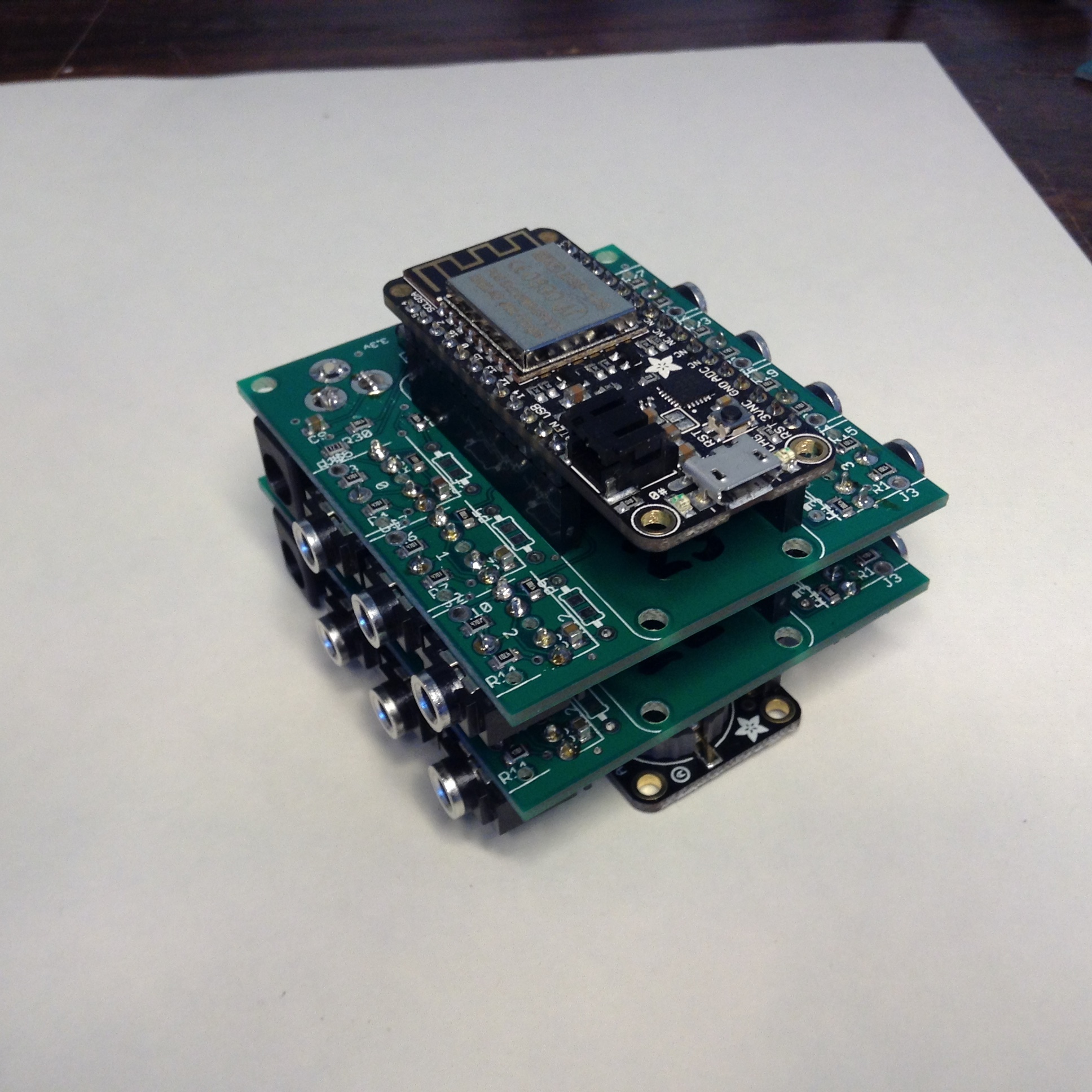
The basic IoTaWatt device looks like this:

On top is the Adafruit ESP8266 feather Huzzah. In the middle is one IoTaWatt ADC shield, and on the bottom is the Adafruit datalogger shield with a real time clock and a 16GB SDcard. The shield has seven channels, typically used as one voltage and six current, so you could monitor six circuits with this basic setup.
Add another shield and you get this:
Seven more channels. Any channel can be configured as either a voltage or current channel, but practically speaking, the first channel on each shield has inputs for both voltage (5.5mm barrel) or current (stereo jack), and related circuitry. So now 14 channels, 1 or 2 voltage and 13 or 12 current.
At the risk of revealing my agedness, here’s what I call the Dagwood Sandwich:
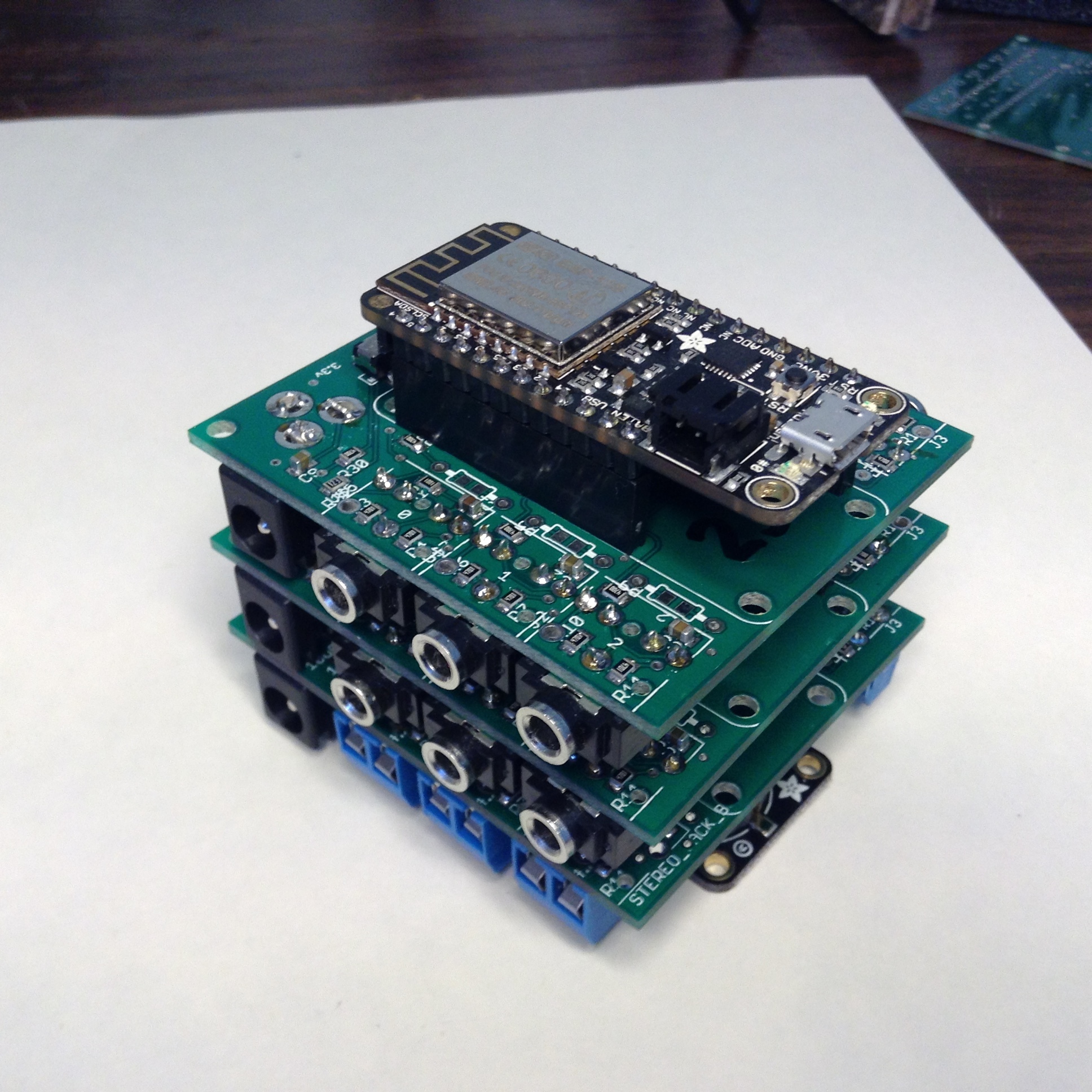
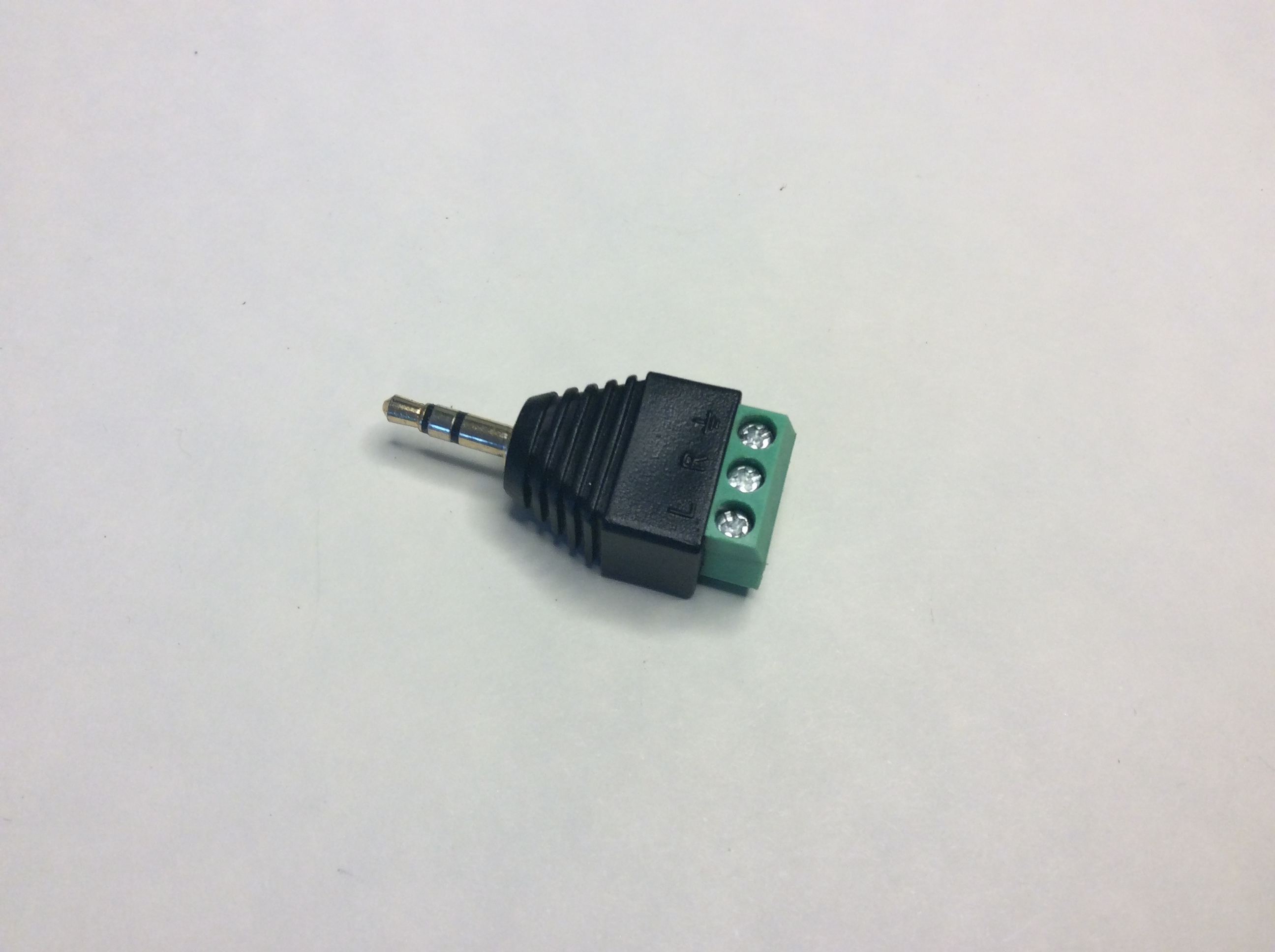
Here the third board is populated with screw terminals for the CTs instead of stereo jacks. Personally, I like the jacks, but for most CTs that requires soldering on a male jack or using these:
Finally, here are the components laid out individually:
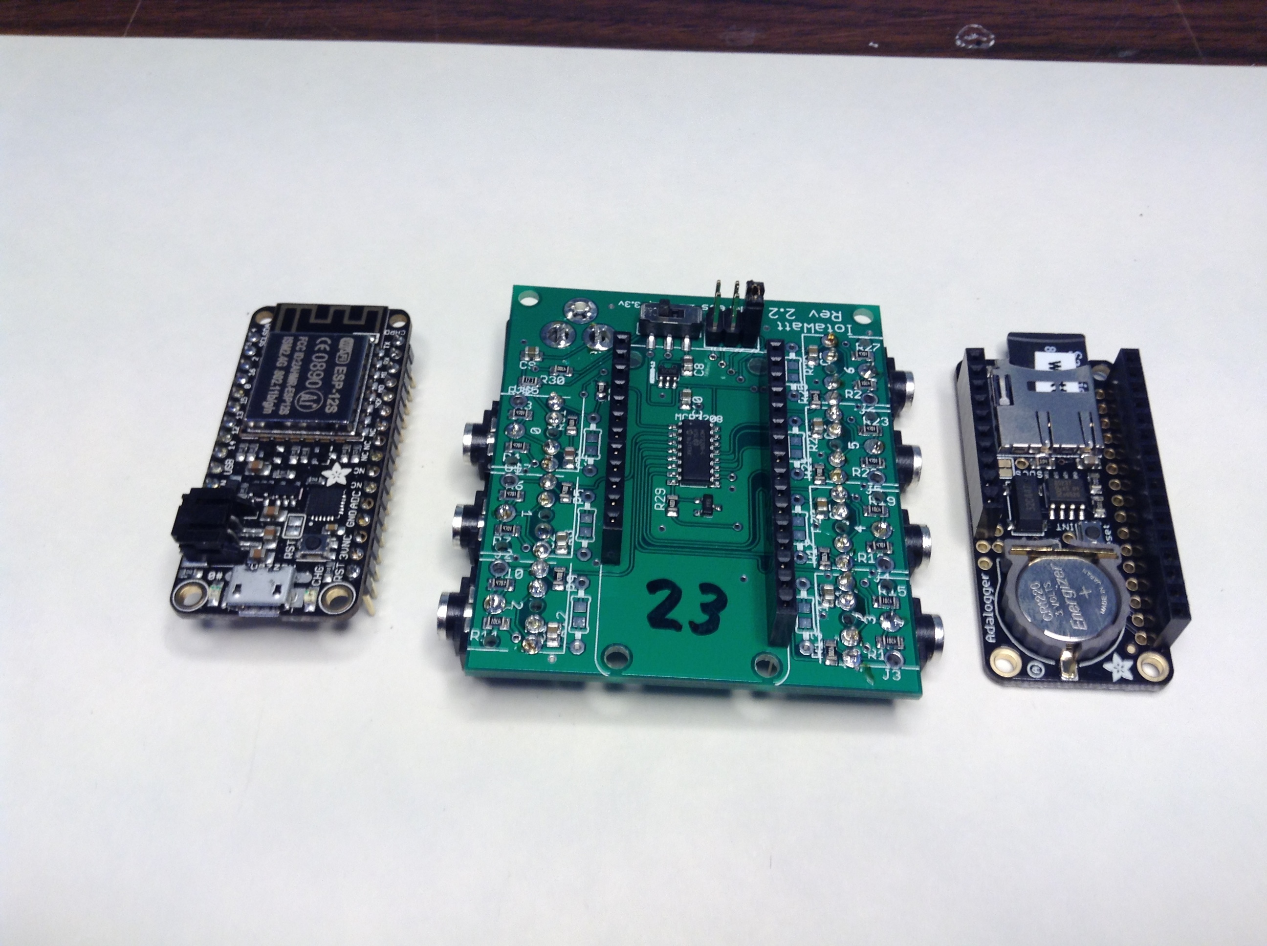
The three position header on the back is a jumper to select address (0,1,2 = chan 0-6, 7-13, 14-20). The switch selects 3.3v or 1.2v ADC range.
That’s about all there is to it. Oh, and installation/use documentation is in the works.