I am new to the community, so please forgive me if this post is super redundant, and please direct me to appropriate threads if they exist. I did a search of past posts before asking this, I swear
Can the Emon platform easily access/record the instantaneous samples of voltage and current? It looks like the default setup is to record RMS values only.
But why? My first assumption would be that you have a rapidly changing or transient condition that you want to measure. If that’s the case, the Arduino platform that we (presently) use, based on the Atmel ATMega 328P, is going to struggle, it’s not capable of storing very much and it’s hard to export the data at the rate it’s gathered.
If you’re up for a bit of serious development, I’d suggest you look at the threads here regarding the STM32. There was a lot of development work published here by @dBC (it seems like about 2 years ago, maybe more), that - even though I don’t know your problem - would lead me to think you stand a much better chance with one of those.
But if you only want (say) peak values (restricted of course by the maximum sampling rate), then starting with our hardware and custom software might be a solution.
The motivation for the project is research - the university I’m working with has a campus microgrid and we would like to install current/voltage monitoring nodes at various points to enable the research. We would indeed like to be able to sample and collect data fast enough to detect transient events if they occur.
A bit about my experience - my formal education background is in power systems, and in the past ten years I’ve held various engineering jobs at utilities, and am currently working as a system integration engineer at a small engineering consulting firm. I have a solid understanding of power system theory and have some coding ability, but I don’t have extensive PCB design experience. That being said, I am quite enthusiastic to learn.
I’d like to design a platform that had at least three voltage and three current inputs that was able to sample and export the instantaneous current/voltage samples at a sufficiently high rate to recreate the waveforms. How tall of an order is this? I’ve been reading about the past development centered around the STM32 that you pointed me to and it looks interesting.
That would very much depend on the time frame, both in terms of the fidelity you require in the recordings (how many harmonics are you interested in) and in the duration of the recording.
As I see it, the immediate and obvious problems are, if you need harmonics up to (say) the 30th, then you need a minimum of 2 × 30 samples × 60 Hz per second, and that’s just one channel.
If you’re interested in transients, then you need to sample continuously to a buffer that’s big enough to hold a few tens of milliseconds before the transient starts, plus however much you need while it dies away, and unless you can dump the buffer to long-term storage as quickly as it’s filled, when you’ve detected your transient, you’re blind to the next transient while you’re emptying the buffer. It’s an interesting problem.
I was only on the periphery of the STM32 development, and it was a while ago, so I’d need to go back and re-read what was done before I could evaluate just how useful that might be to you.
I guess the other question is how to you define/detect the transient? I assume the transient search happens on the V channels? Do you want it to auto-trigger on some anomaly and then capture the data immediately before/after that point (like a 'scope), or do you want it capturing everything all the time for later analysis off-line?
Happy New Year right back at ya’. I’d be inclined to split it in two: have a LAN connected acquisition unit and then use a real computer with a real filesystem to receive the datastream and store it, process it, graph it, archive/delete old log files etc. etc.
@Robert.Wall’s numbers are probably as good a place to start as any: 2 × 30 samples × 60 per second per channel. That’s 21,600 samples per second, or 345.6 kbits/sec (even less if you pack two 12-bit readings into 3 bytes, although I doubt that’s necessary). I reckon an stm32f207 could easily act as 6-channel LAN connected ADC, and just spew the readings out over UDP, maybe throw a msec timestamp in with each batch so you can detect lost packets.
Since you’re not trying to calculate real power you can probably tolerate phase errors, but if not, the time offset of each reading within a message would be well defined - it would reflect the ADC conversion time, so if you were really keen you could potentially reconstruct the exact timing of each sample on the “mainframe” (with further adjustments needed to compensate for any sensor induced phase shift).
You could even have multiple acquisition units spread around the campus and one “mainframe” siphoning all the data off them. I think the stm code would only be a few lines of C - I might even knock up a proof-of-concept implementation next time the rain drives me home from the beach. The real work would then all need to be coded on the “mainframe”.
You can go off people quite quickly, you know . It’s snowing here. There’s about 10 mm accumulated and it’s still coming down, and sticking. Although it’s 0.4 °C outside now, it was -0.2 °C earlier.
@dBC@Robert.Wall - thanks again to both of you for all your great suggestions. A few more questions and clarifications:
This would be ideal. As we get up and running there will almost certainly be server space dedicated to the project.
What would be needed for precision time stamping? If possible, we’d like the data to be able to be used to compare with bulk grid synchrophasor / PMU data (i.e. IEEE/IEC 60255-118-1-2018, formerly IEEE C37.118.1-2011). I believe the timestamp precision required for this is +/-500 nanoseconds. At the very least, we want to have several nodes around the campus with which we’d be able to compare time-synchronized data to some level of precision.
That’s the dream! The campus has two points of interconnection with the bulk electric grid. Campus load is about 12 MW. The campus has about 8 MW of traditional prime-mover generation. 3 MW of solar is being added, along with sizable battery storage. We’d like to have nodes at the grid POI, the inverters, and critical loads to start, with more nodes added over time to facilitate microgrid research.
Do you have any recommendations for an stm32f207 development board? Would the one in the link be acceptable, in your opinion? Is there an IDE for the STM32 that you think is best?
Time syncing could be an interesting sub-project in its own right. Absolute timestamps to that accuracy could be a challenge. Within a logger, relative timestamping of each sample would be pretty good - as good as the crystal you use really so 50ppm say. If you can arrange that all loggers are monitoring a common 60Hz V signal then the common ZX’s they all see might be a good way to align them. That would allow for much more relaxed timestamps because a +ve ZX only comes along every ~17 msecs so you’d just need to make sure you were looking at the right one.
I haven’t really given this a lot of thought, but I’m thinking you might be able to run a PLL on the server for each incoming stream and detect the ZXs there to work out their relative offsets. At those sampling rates you won’t exactly catch a ZX but you can interpolate it from the two readings either side of zero.
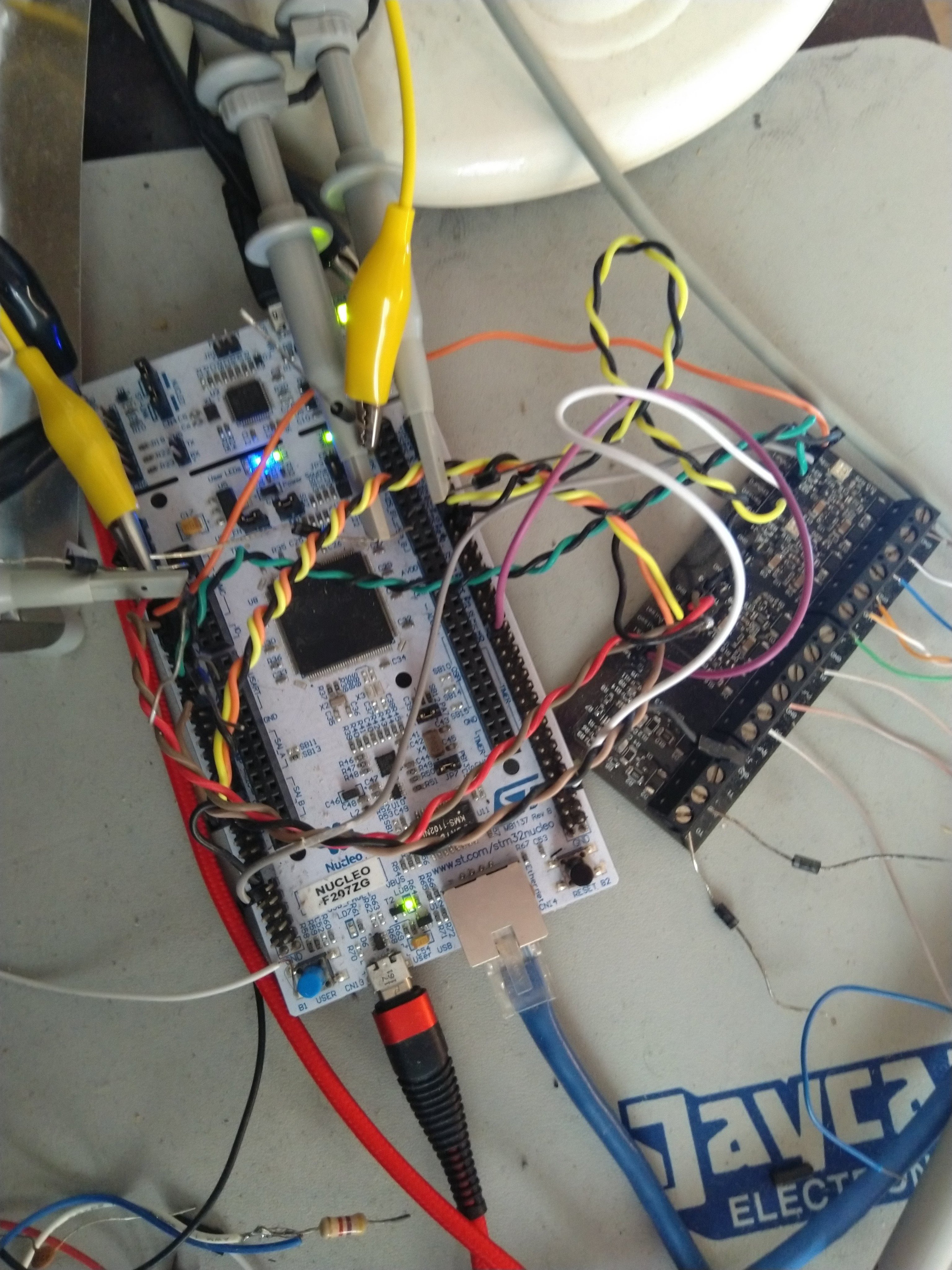
That’s the one I use for f207 prototyping. It’s got Arduino-style headers that expose 6 ADC inputs (and Morpho connectors to let you get at a whole lot more). For initial prototyping, you could potentially start off with something similar to the emontx-shield but without the radio stuff, 3.3V instead of 5V, and 3V+3I inputs instead of 1V+4I. For my Nucleo prototyping I prefer to use the Morpho pins via jumper cables to an adjacent “shield”. That way the shield isn’t covering up all the other pins you might want to probe while debugging:
Actually, I just noticed the MAC on the f207 supports PTP so you could potentially have lots of fun with that on all your remote loggers and your server.