I now have my heat pump board working and receiving data on my pi whit emoncms.
Also have 3 emontx working and sending data to the emoncms.
On the heat pump board I have 3 CT sensors, a Kamstrup Mbus, a pulsmeter and a temp sensors connected.
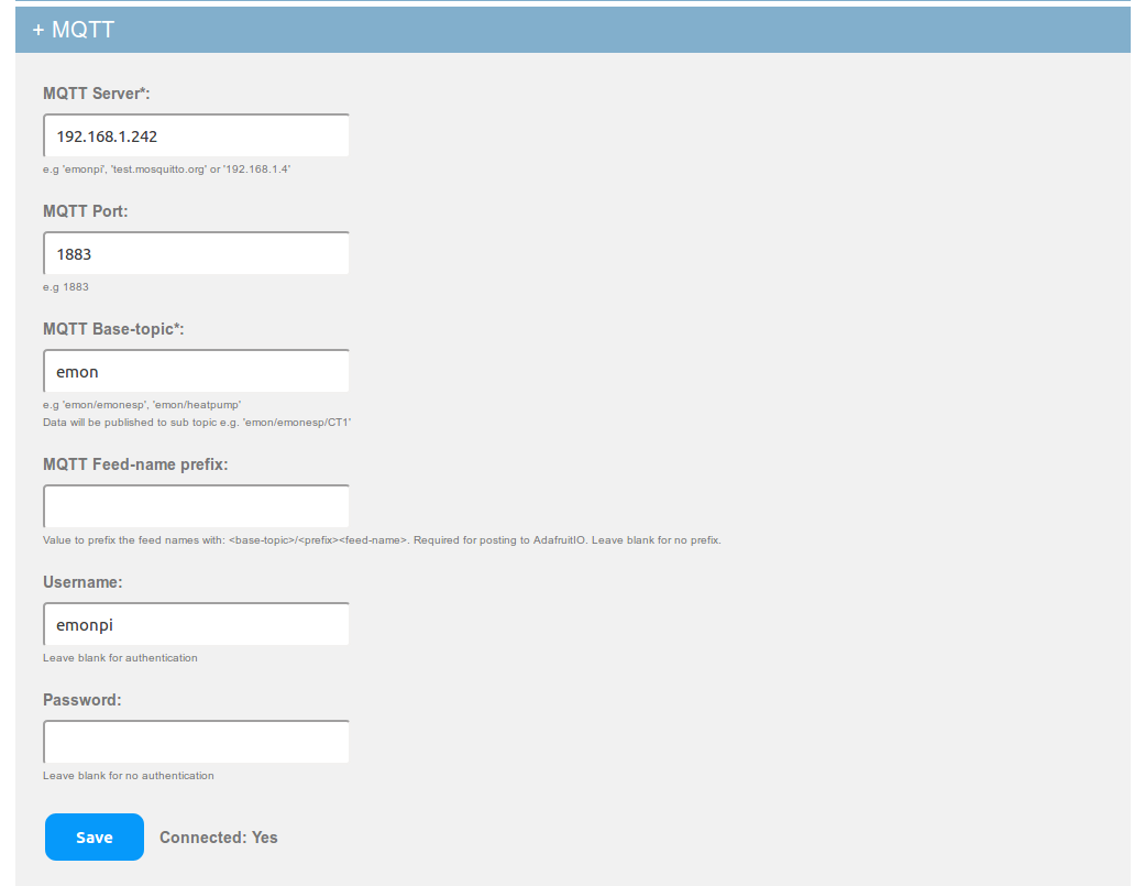
The heat pump Wi-Fi is connected, but the MQTT server keeps saying connected: No
On the emoncms the input view looks good. I see all the value of the 3 EmonTX
Also I see the inputs from the heat pump board.
Looking to the result my heat pump has a COP form 41. That would be very nice but can’t be true.
In the emonhub log I only see the information (MQTT) from the EmonTX, the EmonTX using node 13, 14 and 15. When I update the emonhub, the config file becomes extra node files that collapse whit the MQTT inputs. I have to delete these.
But there are no lines from the heat pump board. In spied these do come in. where can I find these to correct the config values.
I would like to make a serial print and input for the Voltage and Current for each CT to calibrate.
Good point! Is there a chance the heatpump controller board and central heating pump could be on one of the phases and then the main compressor across all three?
Given that the CT inputs on the heatpump board are intended only for indicative power monitoring the error might not matter that much - for higher accuracy monitoring with the heatpump board I recommend using the pulse input or Elster A100C IrDa reader (though that’s a single phase meter - I couldnt get the Elster A1100 3 phase meter IrDa to work)
The “ancillaries” probably are single-phase, and they’re probably not that significant in relation to the compressor. But without knowing the powers and power factors, it’s impossible to say with certainty. However, with the pump being around 10% or less of the compressor’s rating, then provided you measure the current on a phase that isn’t powering the pump, the result should be reasonable (but low). If you measure the one that is, the result will be high and the error bigger.