The video is on a 3rd party host. If you can describe your problem in words, this thread might be useful to someone else in the future who’s trying the same approach. As it is, if that external video gets deleted, your question and any answer is all but worthless.
Is the 1.65 / 2.5 V centre rail correct? Is the op-amp oscillating?
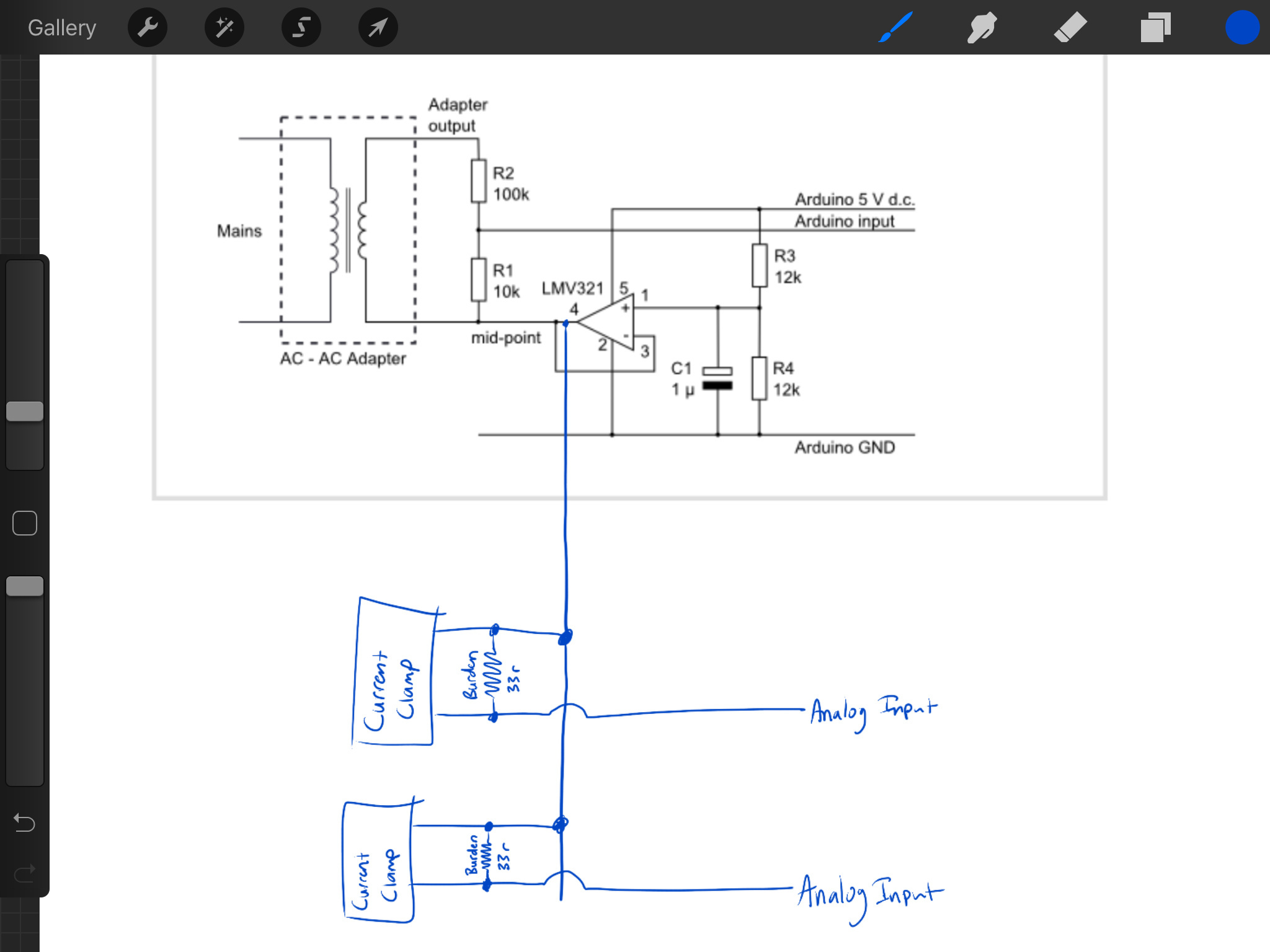
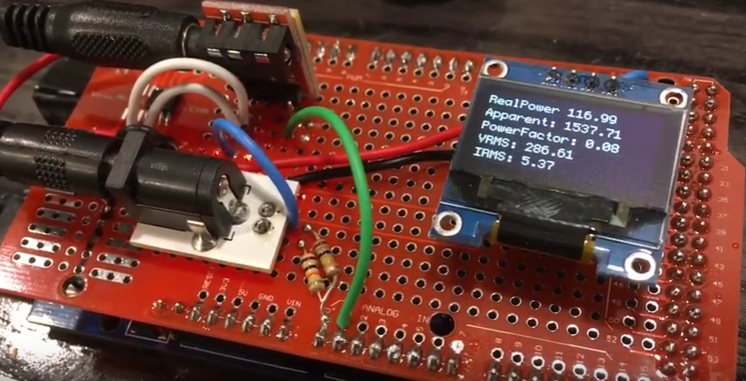
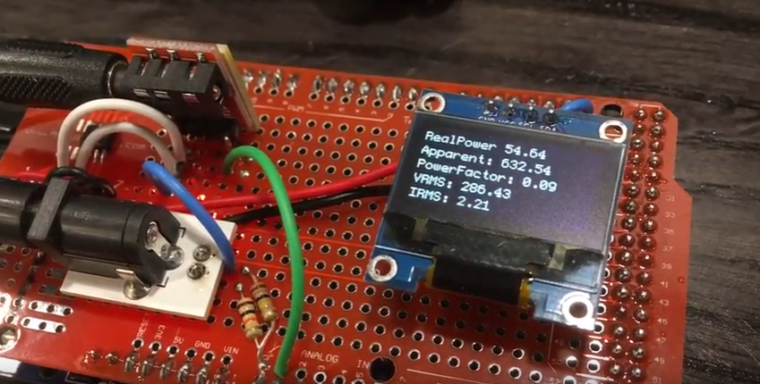
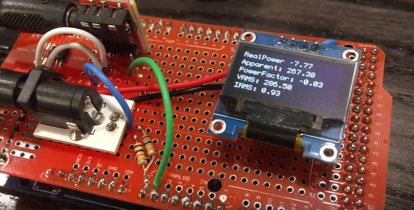
286 V rather than 240 V is probably only a calibration problem - is it relatively steady? Where does the voltage come from and have you used the divider on your circuit diagram?
What c.t are you using, and what is its calibration factor?
Are you using your own sketch, or one of ours. If so, which?
To be honest, this is heading for “stupid question” territory because you’re asking for help but not giving enough background information to allow me or anybody to work out what the real fault might be and to rule out a whole host of other possible causes.
You can probably do a lot with a voltmeter. If you suspect the Op-Amp is bad, it’s basically a DC problem and lends itself well to checking out with a voltmeter. Does it have the +5V and Gnd? Is it putting out ~2.5V?
Checking the ADC inputs for that same DC bias is straightforward. Then, if your meter’s AC accuracy is halfway decent, switch over and see if you can see the AC (with respect to ground) at the ADC input. The AC adapter voltage input should be pretty clear. You need a better meter to read the relatively low mv AC that the CTs will produce.
If all that looks good, it starts looking like the code.
As it’s a breadboard lash-up, I suspect the op-amp has taken off, but at this stage that’s only a guess. The op-amp getting hot could be an indication of that.
What are you doing with the second half of the LM358? Unconnected? The best would be to connect the + input to the divider, the - input to the output (i.e in parallel with the half you’re using, but not using the output).
Looking back, this certainly was stupid question territory. I was deep into complex, needs-to-be-organized code, and should not have been messing with a SMD op-amp for a first try at this circuit. I believe I had multiple problems.
All is good now. I took a few steps back, bought an 8-DIP LM358 and started fresh with the EmonLib Voltage + Current example and wired it up cleanly on a solderless breadboard. So, I created the exact circuit shown in my first post, used the EmonLib example, and that worked great.
The only oddities I had were some unknowns re: calibration values. I believe it’s configured as it should be, but I’ll start up a separate thread to verify I’m calibrating it right.