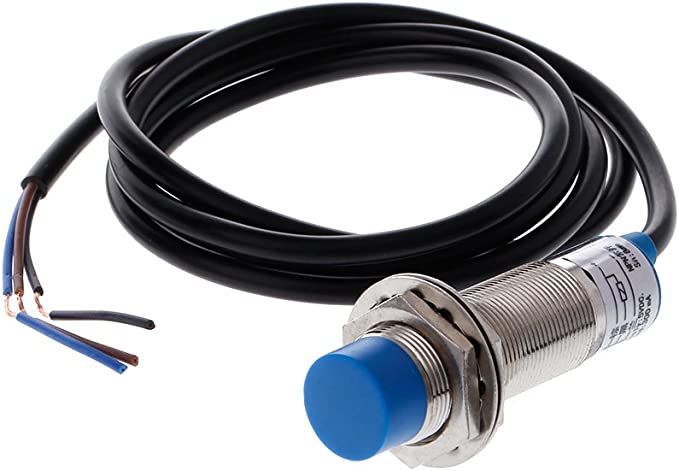
I would like to be able to read my watermeter. Unfortunately it has no blinking led or something so I think I’m kind of stuck to this inductive proximity sensor:
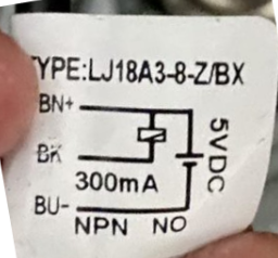
LJ18A3-8-Z/BX 5V
This is a so called NPN N-open device. It has 3 wires: Ground, +5V and pulse.
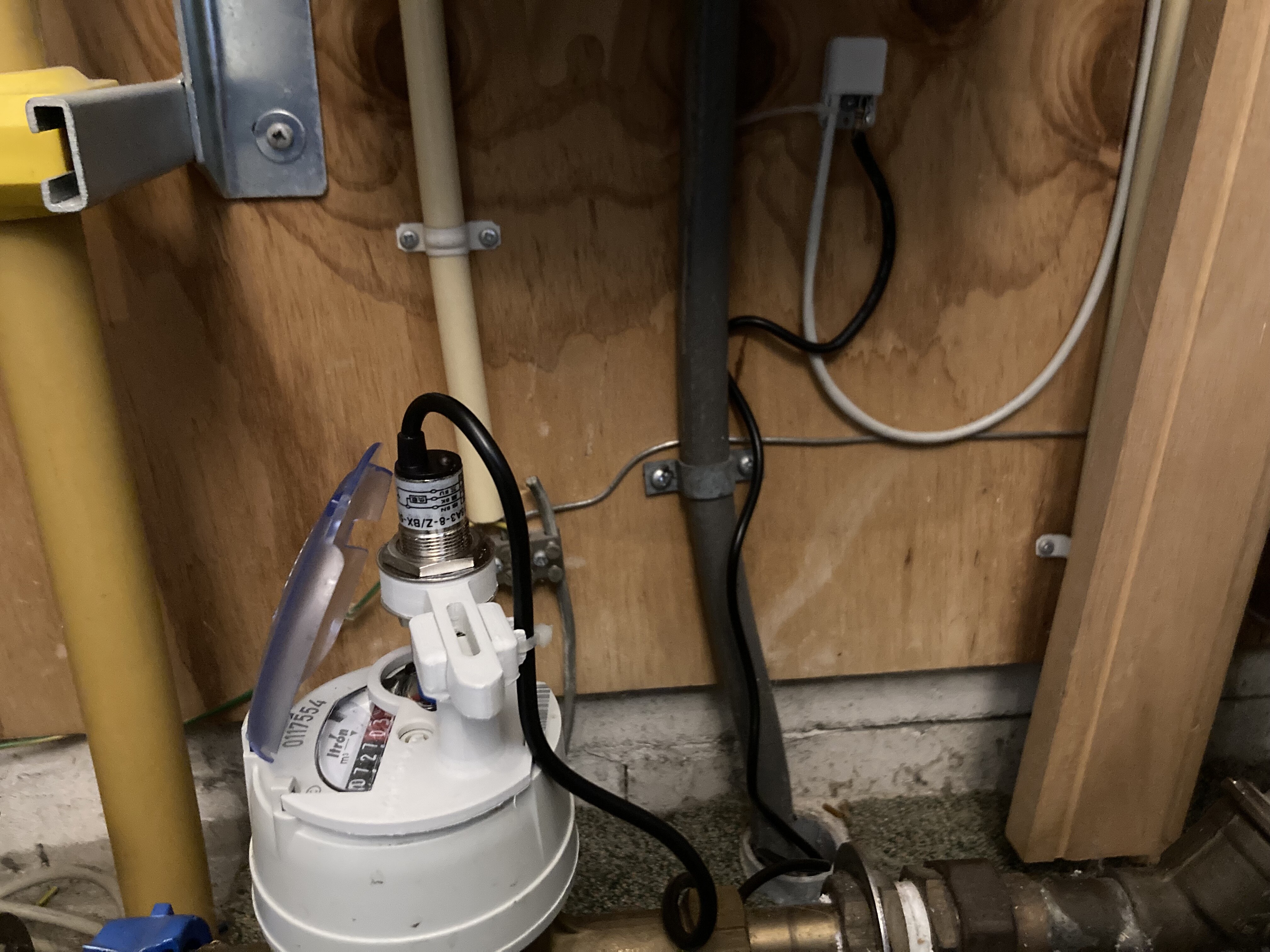
The watermeter has a piece of metal on its rotating liter dial. The sensor will give a pulse when it is ‘near’.
Now I could set up a leftover raspi2 and connect this sensor to it’s GPIO and have a script to send it to my Emonpi.
But it would be much nicer if it could be connected to the Emonpi directly.
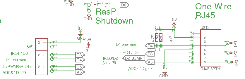
I have an Optical Pulse Counter connected which I only used for ‘calibrating’. (My smart meter only has one blinking led for both incoming and outgoing power.) So if the OPC has a comparable pulse mechanism as this proximity sensor I could use that RJ45 connector. Does anyone has an idea about this? (I don’t dare to connect as a test, because I might ruin something.)
If the OPC-input is not usable, I could connect it to the GPIO of the Emonpi. But how can I get the pulses registrated in a neat way in EmonCMS? Any suggestion anyone?
I don’t see why you cannot use your proximity detector, but you will need to do some interfacing.
What you’ll need to do is supply it with the 5 V available on the RJ45 connector on pin 2. However, it’s not safe to connect the output directly to the pulse input, you’ll need a pair of resistors to divide the voltage down to 3.3 V. You’ll need a 4.7 kΩ connected between the sensor output and the pulse input (pin 6) and a 10 kΩ resistor between pin 6 and GND (pin 5).
I didn’t understand what a “N-open device” is - it is not a term we use in the UK but we use the very similar N/O meaning a pair of normally open contacts (and the corresponding N/C - normally closed). We would call your sensor output “Open-collector”.
You can still use the same two resistors, but arranged differently.
Connect the 4.7 kΩ between BN+ and BK where the relay coil is shown in that diagram, and the 10 kΩ between BK and BU-.
When the metal is detected, the pulse input will be a logic ‘low’ at around 0.3 V, and when the metal is not present, the voltage at BK will rise to about 3.3.V and the pulse input will be a logic ‘high’.
What you are doing is dividing down the 5 V to 3.3 V all the time, but when metal is detected, short-circuit the 3.3 V to GND with the transistor inside the sensor.
If your emonCMS has the ability to send commands to the Atmel processor that handles the pulse counting (Admin → Serial Monitor), you should be able to stop emonHub (turns off energy monitoring) and reset the pulse count, then turn emonHub back on so that it resumes sending the data to emonCMS.
Sending “?” lists the available commands.
Works!
And in the input I did an addition to set the rawpulse count to the correct current overall counter (which is needed to be able to make corrections in case the pulse counter is not working).
Thanks @Robert.Wall !