The only problem now is the reported voltages are not correct.
My multimeter shows ~3.2 while bms shows ~3.6.
Multimeter is 5v on a wall 5v power supply so i assume its correct.
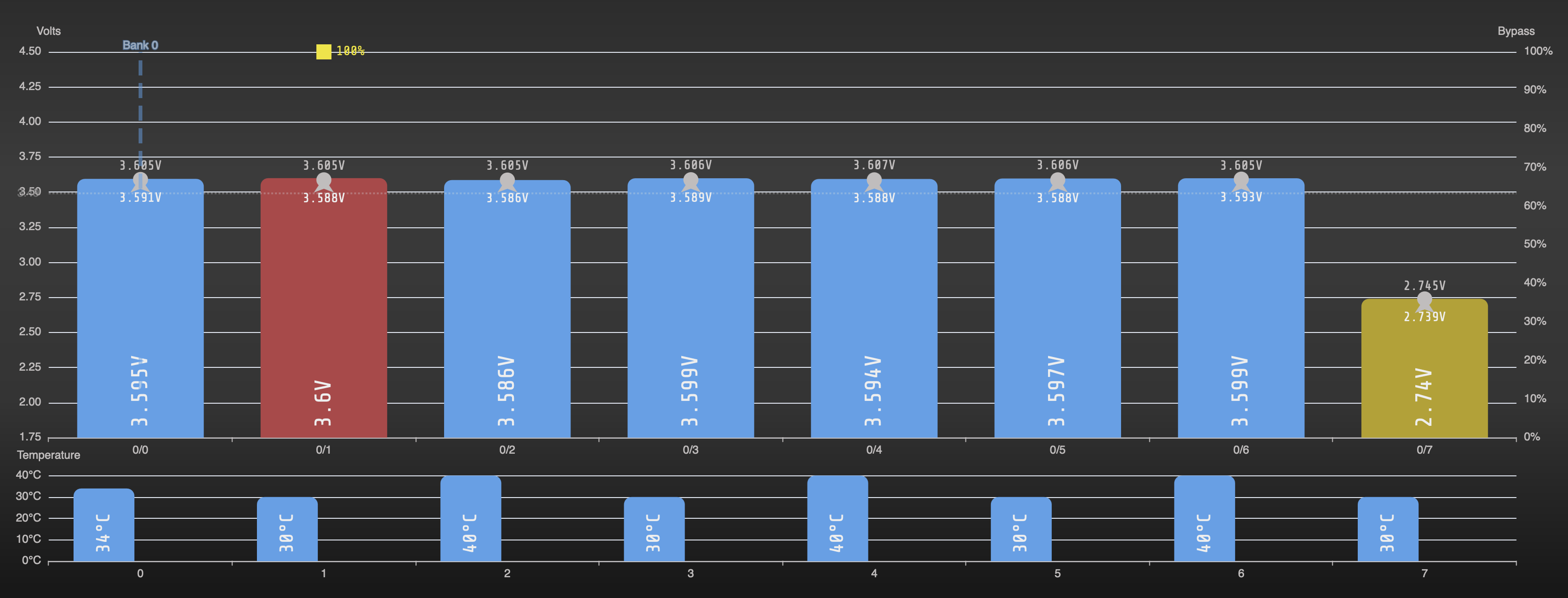
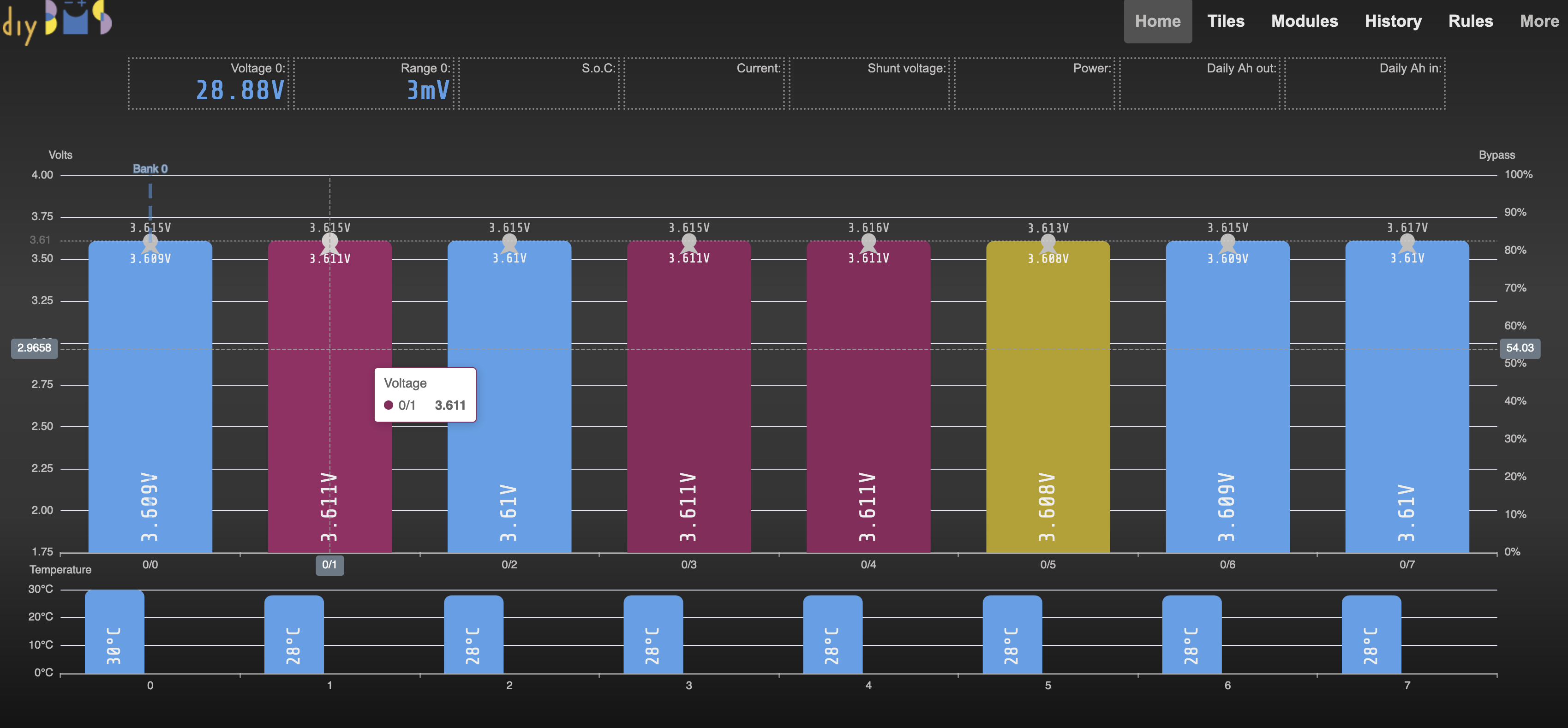
I have the opposite situation where all the reported cell voltages are about 0.32V below the voltages I measure at the 17pin screw terminal! The twelve cells are all between 3.61V to 3.63V measured at the screw terminal connector (and at the cells) diybms is reporting voltages between 3.291V and 3.302V, could this be a firmware issue?
Also is anyone able to confirm the LED behaviour on the 16S All in one board?
On GitHub @stuart has listed the Error LED flash sequences - does this apply only after writing the firmware or is it the same during normal operation?
I have tried two All in one boards and they both report the same low voltage and the LED is flashing but not in a constant pattern, mostly two short flashes with a wait afterwards, but sometimes up to 7 short flashes with a slightly varying wait between them.
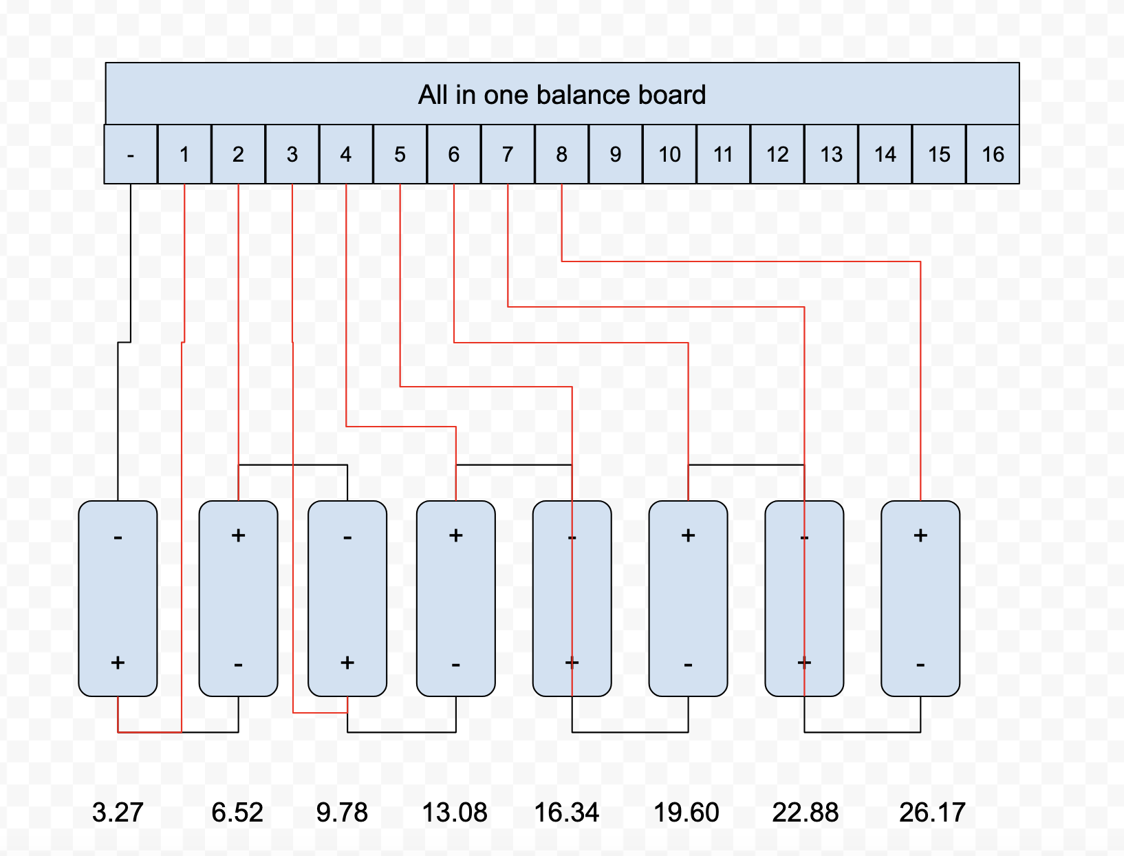
The cells are arranged as 12S ( Samsung SDI battery module from a Range Rover Hybrid) and currently measures 43.5V across all 12 cells diybms reporting 39.59V.
Any suggestions to resolve this would be appreciated.
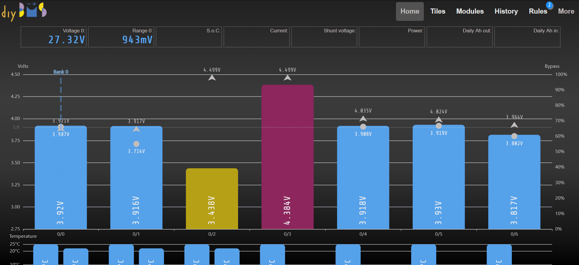
I purchased an all in one board a couple months back and I’m finally getting around to putting it to use with a 7s 18650 pack I built. I got everything wired up correctly and all cells showed the correct voltages. However, over the course of a few hours cell 0/2 slowly decreased in voltage and cell 0/3 slowly increased. I checked each cell with a meter at the connector and they ALL show around 3.8v to 3.9v. The web interface shows voltage values that are within .01 volt of what I found with my meter on all cells except 0/2 and 0/3. Could this be a hardware issue? Does anyone have any recommendations as to how I would start troubleshooting this?