I’m trying to understand why the kWh consumption recorded using the CT current sensor into the emonTx4 is significantly different to that recorded by the meter on the supply to the heat pump. I’m using a 100 amp CT sensor on the heat pump supply, on the live wire supplying the heat pump. The meter is marked as a DDS353 which is about 5m further down the cable towards the heat pump, at a switch for isolating it. The CT sensor is rather loose on the wire, and I have tried moving it around a little to see if it makes a difference to the readings.
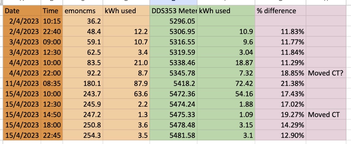
The difference in kWh readings is consistently higher with emoncms, and I have been tracking the consumption for a few days now. It is between 11% and 19% higher which seems very odd. I have also noticed that my grid import kWh is recorded noticeably higher in emoncms than it is from Octopus and by the Tesla Powerwall, again this is using a loose fitting 100 amp CT sensor.
Can anyone shed any light on the discrepancies I’m seeing?
I haven’t tested the sketch you’re probably using for accuracy, but that doesn’t sound right.
Is everything as it came from The Shop?
Where are you reading the values? Is that scaling the numbers?
Is your voltage reading correct - or at least close to that of the other meter(s)?
It should be loose. It has a ferrite core, and while it would be quite difficult to apply any mechanical stress to the core, if you did you’d risk cracking it, and the c.t. would need replacing.
I’ve never managed to get an accurate measure of the difference the wire position makes - I’ve not had time to try a measurement with the 0.333 V c.t; the influence using a YHDC 50 mA output one was discernible, but too small to measure consistently. What is likely to have a greater effect is a very close current-carrying cable - and it still needs a lot of current. Again, I’ve not tried to measure it with the 0.333 V c.t., the number for the YHDC c.t was 160 mA when a coil with 100 At (equivalent to 100 A in a single wire) was touching the case - in the most sensitive place. Your average power is about 100 W, about 40 mA, this is worth checking.
As Robert asked, did it all come from the shop together and you have not used a CT from another source or an old setup? The CTs are different (in some cases).
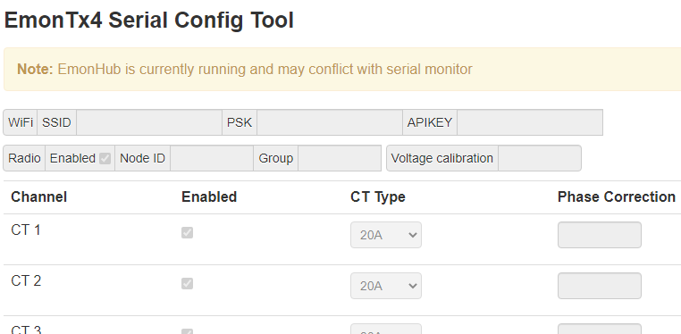
Is the CT channel on the TX4 correctly configured for a 100A CT?
I really grateful for the replies - thanks so much.
Yes, I bought the 100 amp CT sensors from the shop. I configured the Tx4 using the serial USB tool, and the inputs do seem to be being interpreted correctly. I’m reading the numbers from the feed - it is simply a Log to feed followed by Power to kWh, no scaling. I then read the value at the same time as I read the value on the DDS353 meter and compare the usage.
The voltage value on the Tx4 is similar to that shown by a simple meter plugged in at another part of the house. e.g. the Tx4 reads about 0.4 volts higher most of the time, sometimes closer for example 237.4v vs 237.2v.
I have now placed both of my 100 amp current sensors onto the heat pump cable and they seem to be giving the same values, but I will monitor them today.
Overnight, the discrepancy between the Tx4 kWh and the DDS353 was about 21% 6kWh vs 4.9 kWh…
Why the choice of 100 A c.t’s? I can’t see a heat pump pulling 100 A even on inrush when the compressor starts.
How do the instantaneous power values compare, both when the heat pump is running and when not? While current is the basic unit, it isn’t normally sent to the serial monitor, power is the next basic unit where a comparison is more meaningful.
Of particular interest would be the power when the heat pump is not running.
I had to get the 100 amp CT’s since the cables I could monitor were about 10mm diameter, which is too big for the 50 amp CT’s. You are right, the heat pump never demands that much!
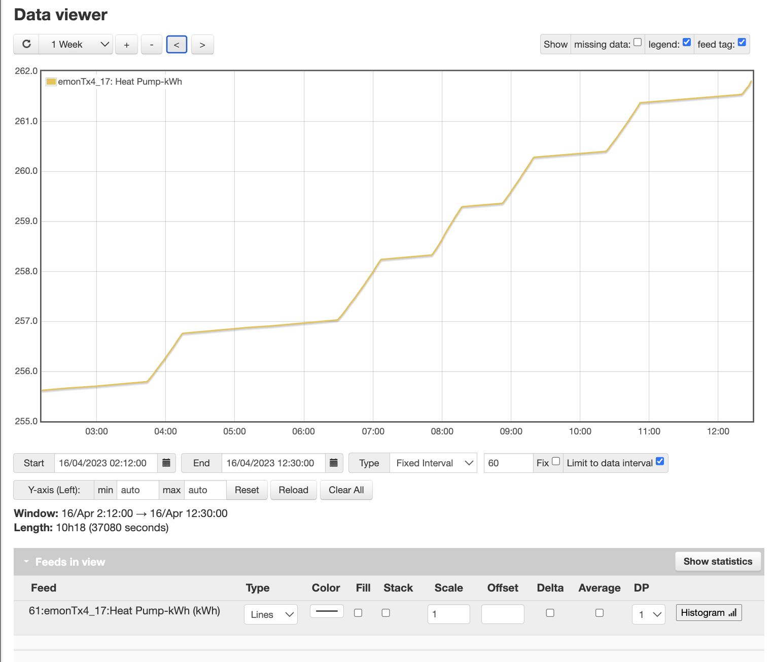
The heat pump and associated pumps and the controller are all served by the same 32 amp supply. When the heat pump is idle, it draws 115w. Right now it is running and the draw is showing as 1834w and 1837w on the two CT’s I now have on the cable. Both sensors are reading essentially identically.
This is the visualisation of the heat-pump-kWh power feed for the last few hours.
I will try putting a 100amp CT onto one of the other feeds I already have fitted with 50 amp CT’s. I will be even looser, but maybe it should still work? I’m happy with the accuracy of the solar generation feed, for example, which has a 50 amp CT sensor fitted. That would give me a way of comparison, if it works …
I seriously wouldn’t worry about the position of the c.t. on the cable. It won’t make 10% difference. An adjacent cable might, especially to the 115 W idling power, but not averaged over the 9 hours I can see there.
According to who? The emonTx4 or the DDS353? I’m afraid you’ll need to count and time pulses for that - 1 pulse = 1 Wh. You should see 1 pulse every 31.3 seconds.
1834 W should give you 1 pulse every 1.96 seconds, so you’d need to count 10 or 20 pulses for accuracy.
I went to look at the meter pulses when the heat pump was idle when only the controller and circulation pump were running. And there was no pulse. Not every 31.3 second, not at all. So, the penny has dropped. The meter does not measure the overall power being consumed by the installation - just the heat pump unit itself. So the wiring inside the DIN wallbox switch must have been connected only to the heat pump circuit. So, the background 115w consumption is just not being counted by the meter, but the overall supply is what my CT sensor is monitoring. 10 hours of 115w overnight accounts pretty exactly for the difference I am seeing.
I can relax now. I have learnt a few useful things on the way, and I am very grateful for your replies.