My problem is with my well intentioned neighbour who has twice offend me the loan of his "oil filled Electric heater given that I am obviously in trouble. "
My other neighbour is a care home , who would not appreciate large clouds of Water Vapour/Stream.
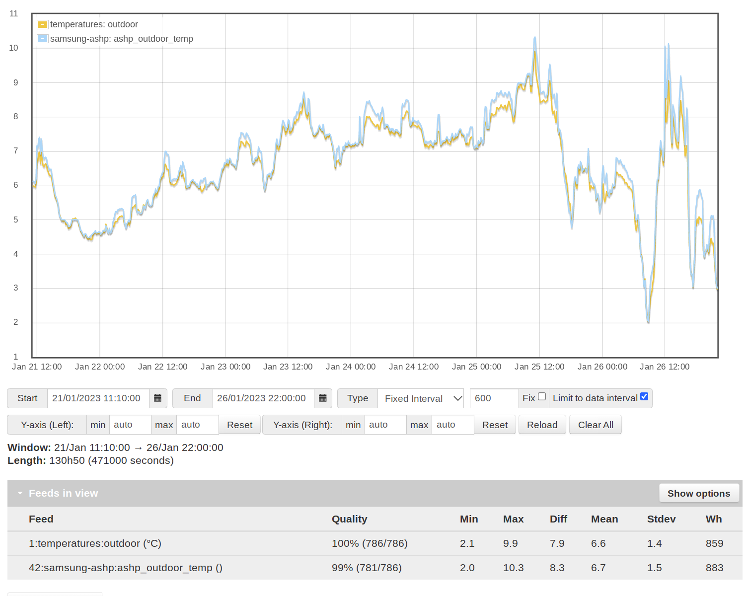
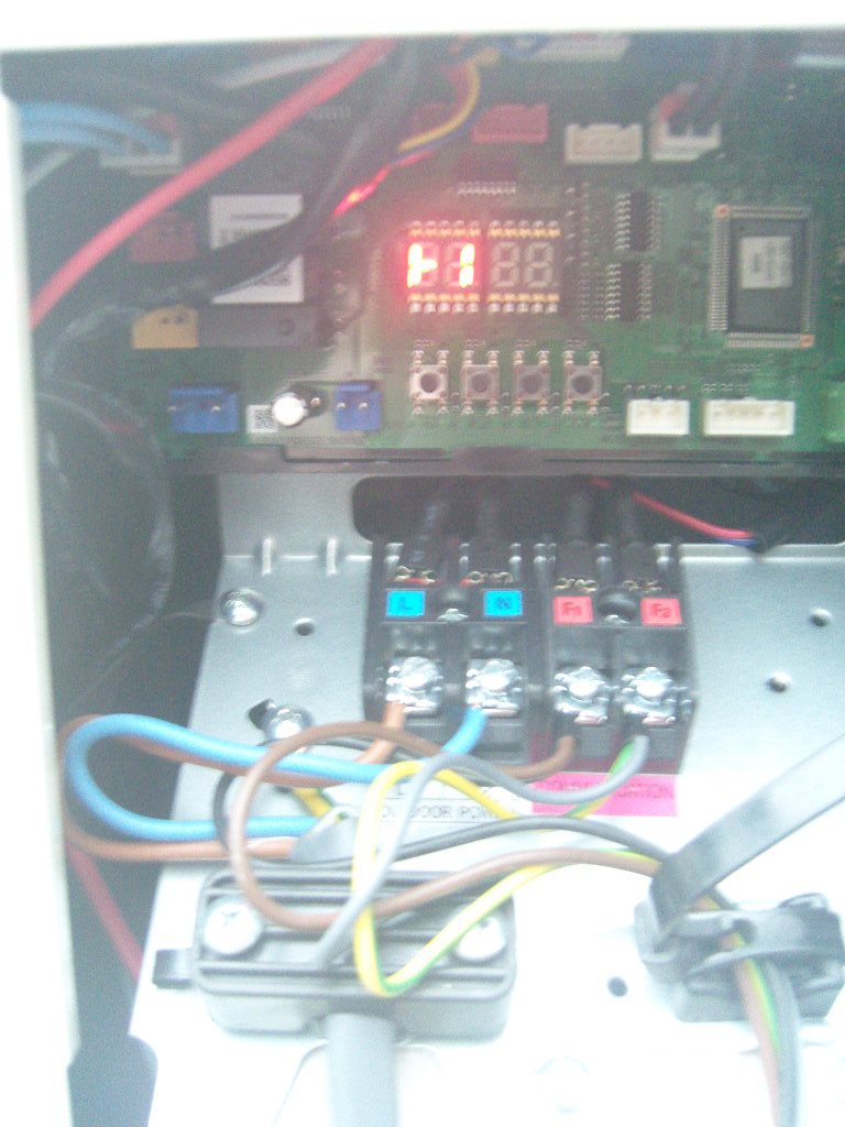
As to the External outdoor sensor , apart from the photographed sensor I have none!
My “installer” did not install five major components in his “installation”.
I would not be the least surprised to find a sixth missing external Thermistor.
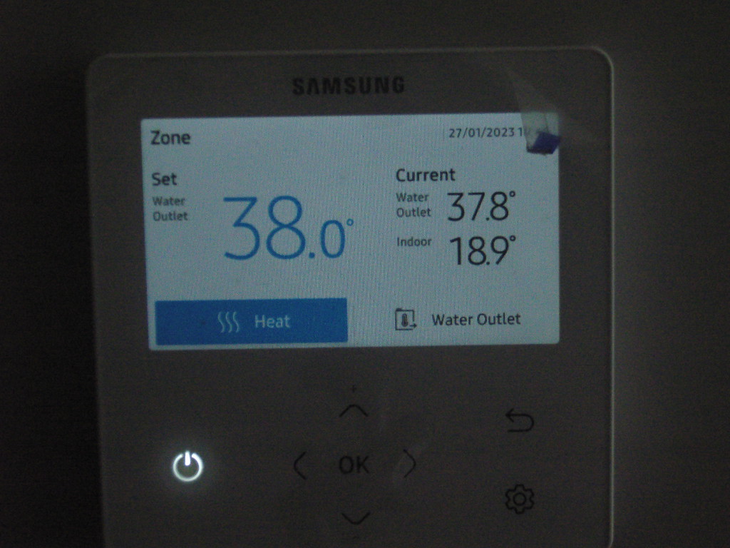
However, Now, I have only the projecting Air Thermistor. It must now be used to measure the outdoor temperature for Weather Compensation.
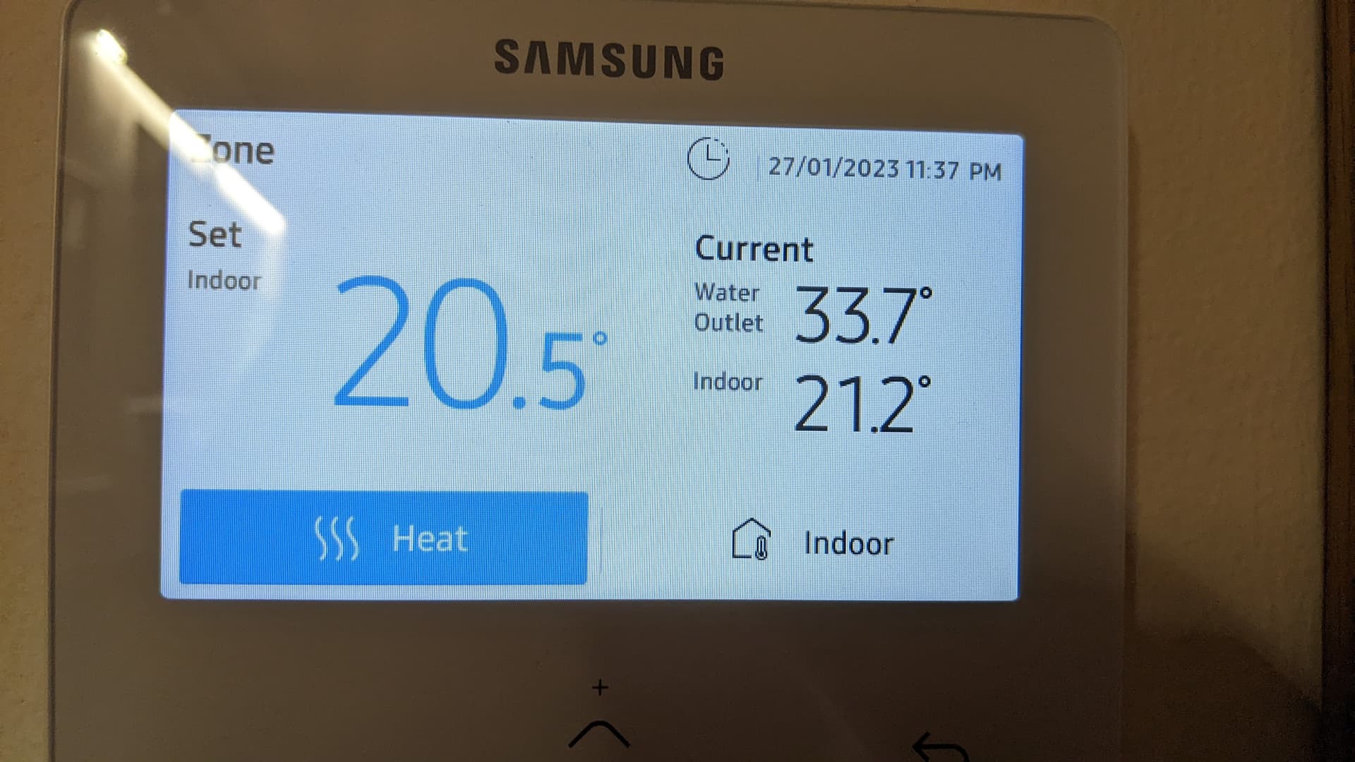
My major complaint is the instability of the Weather Compensation system, with the Heat pump , on two occasions charging the Flow water Temperature up to 65 C, with an accompanying display of white Vapour!
I must assume that the Thermistor is “probably” the culprit.
Again , many thanks Colin, I need to appreciate others experience.
My “installer” has now said that “he will attempt to get Samsung to Repair and upgrade my Samsung Heat Pump”.
We have a Vaillant heat pump so the controls etc are a little different to the Samsung, I am using the OEM controls as they work perfectly well for us.
I have now had a hunt through the Samsung installation manuals and see no mention of the outdoor temperature sensor, so it may be built in to the outdoor unit itself, as you had suggested. This seems strange as manufacturers are normally quite particular as to where the sensor can be mounted, but they must have designed this issue out.
Someone else with a Samsung can hopefully confirm the case with this sensor.
Meantime, I hope the Samsung tech can carry out some tests on your system and make sure it is working as designed. There is a Samsung Gen 6 on the heatpump dashboard performing really well, so hopefully you can get similar performance.
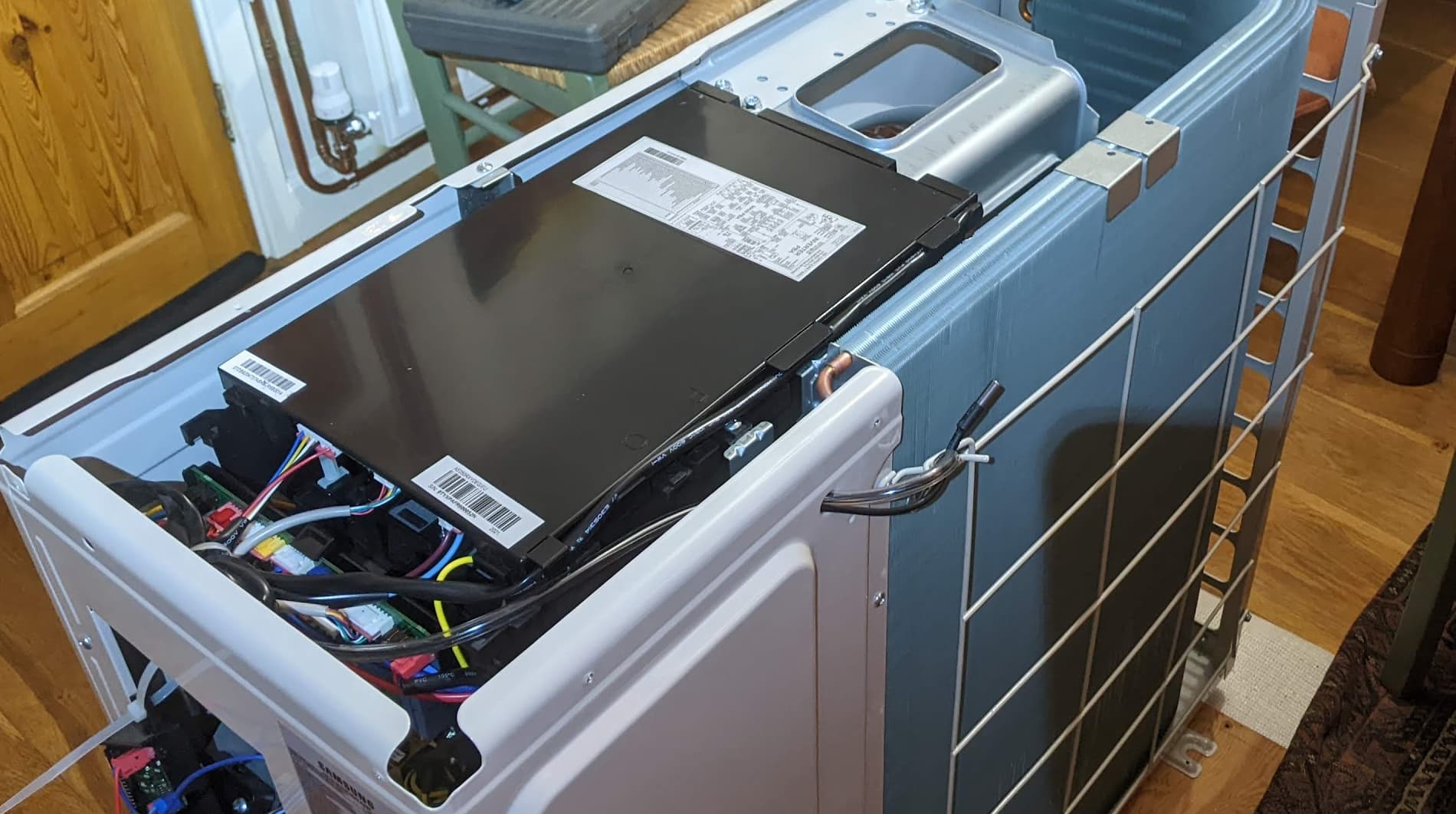
I have a Gen6 Samsung, there is definitely an outdoor sensor located on the rear of the unit. Here’s a photo of the unit with the top cover removed, I added a 2nd sensor next to the original sensor for extra monitoring:
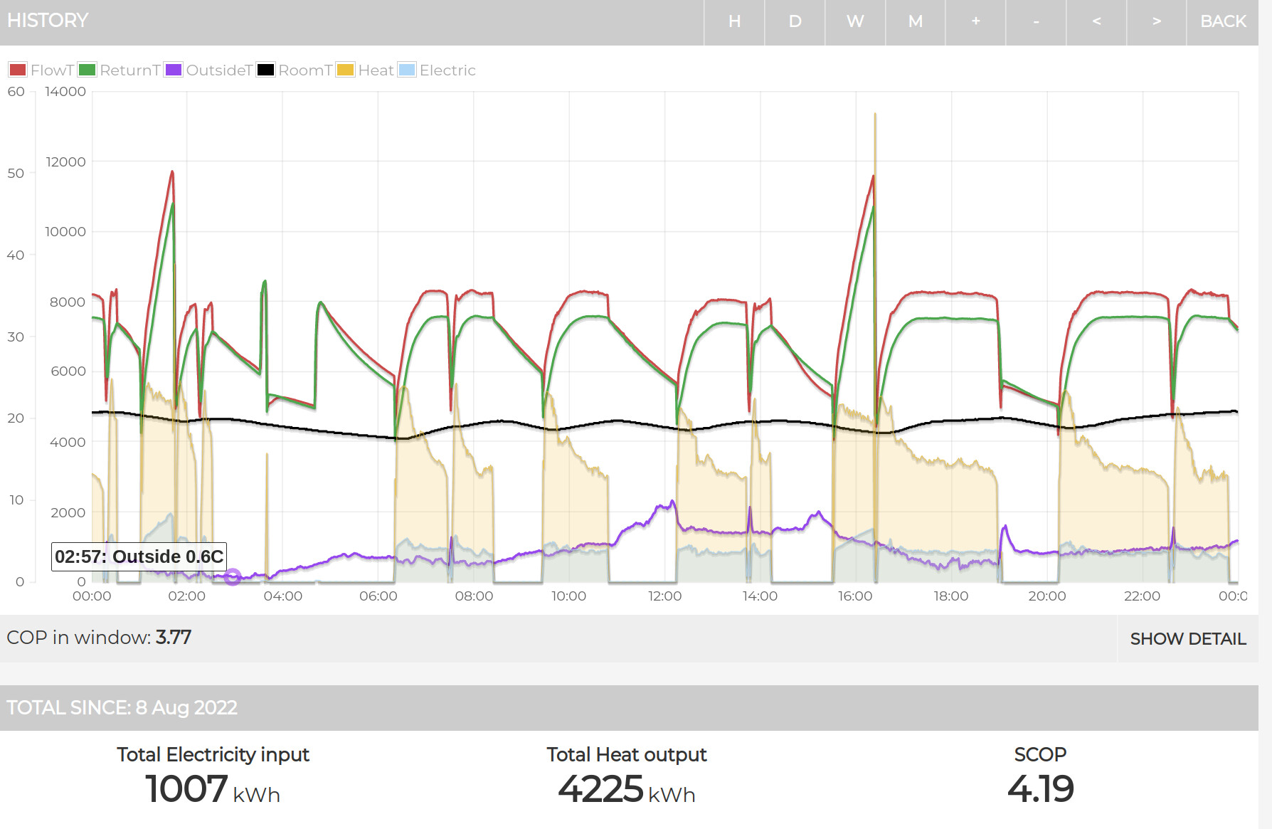
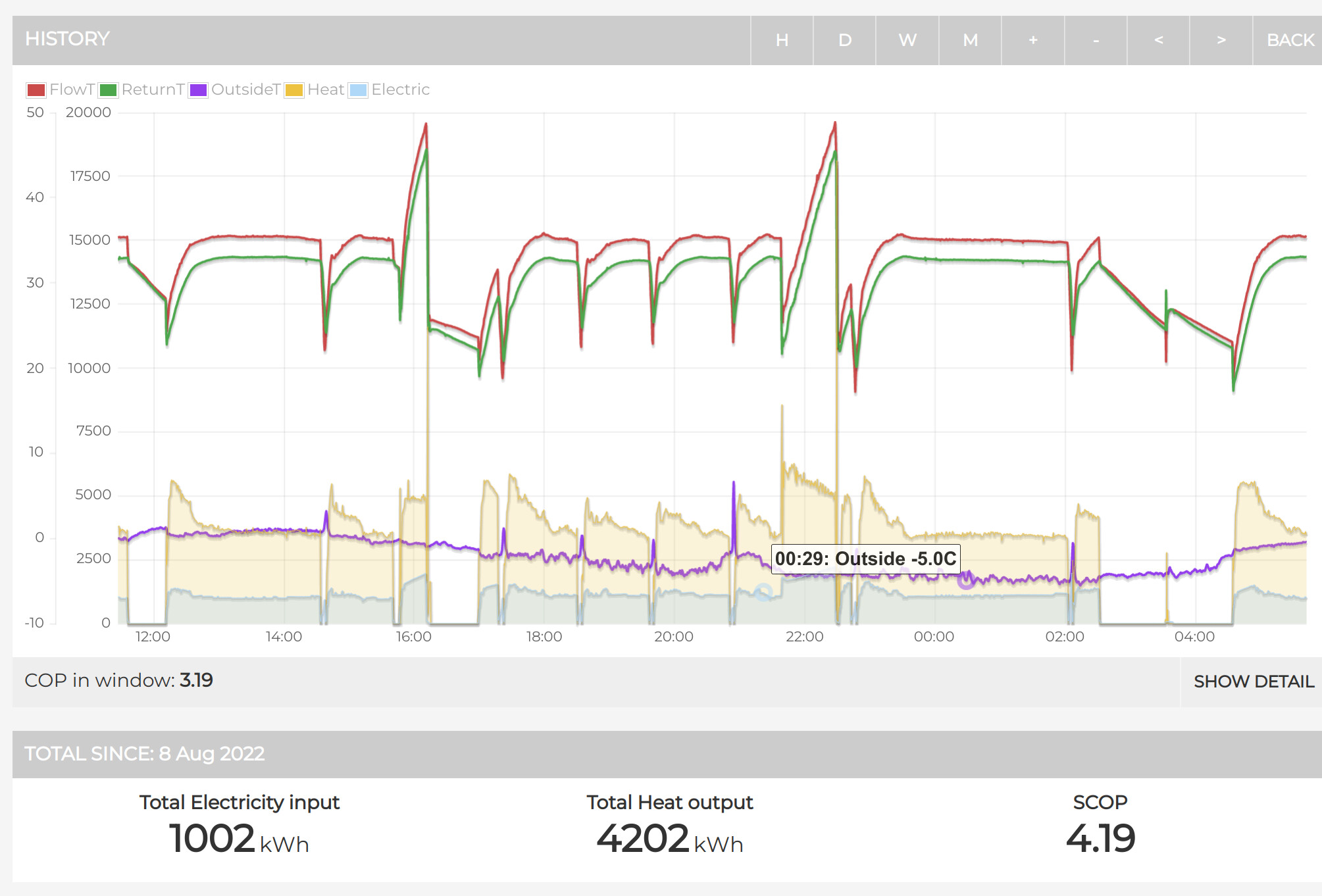
My retrofit 5kW Samsung is performing well using stock controller and upgraded radiators, SCOP of 4.2 since installation in Aug 2022. Here’s a link to live data from my unit: Emoncms - app view dashboard
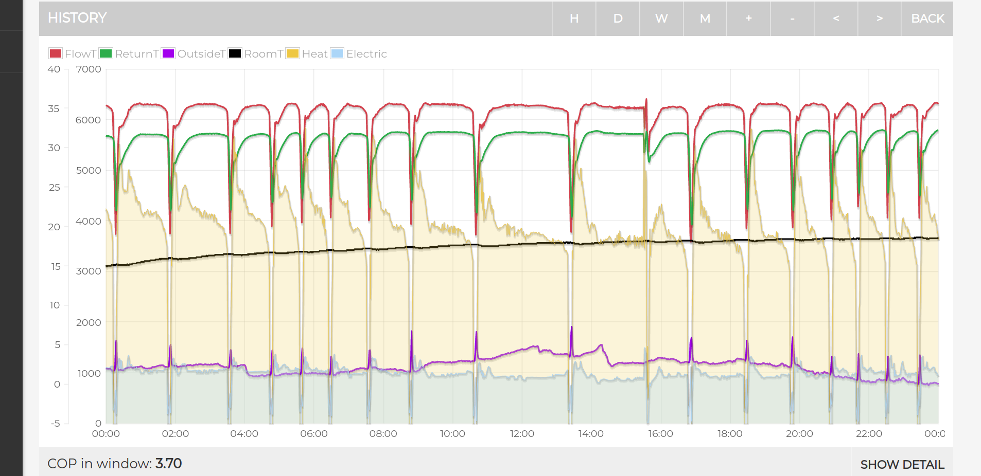
Defrosting with the accompanying steam is quite normal, all heat pumps will do this when the outdoorT is low, it uses a small amount of energy, my measurements show 0.088kWh per defrost, at about 0C outdoorT my Samsung defrosts every 1.5hrs, but the overall COP is still 3.7 which is good in these temperatures.
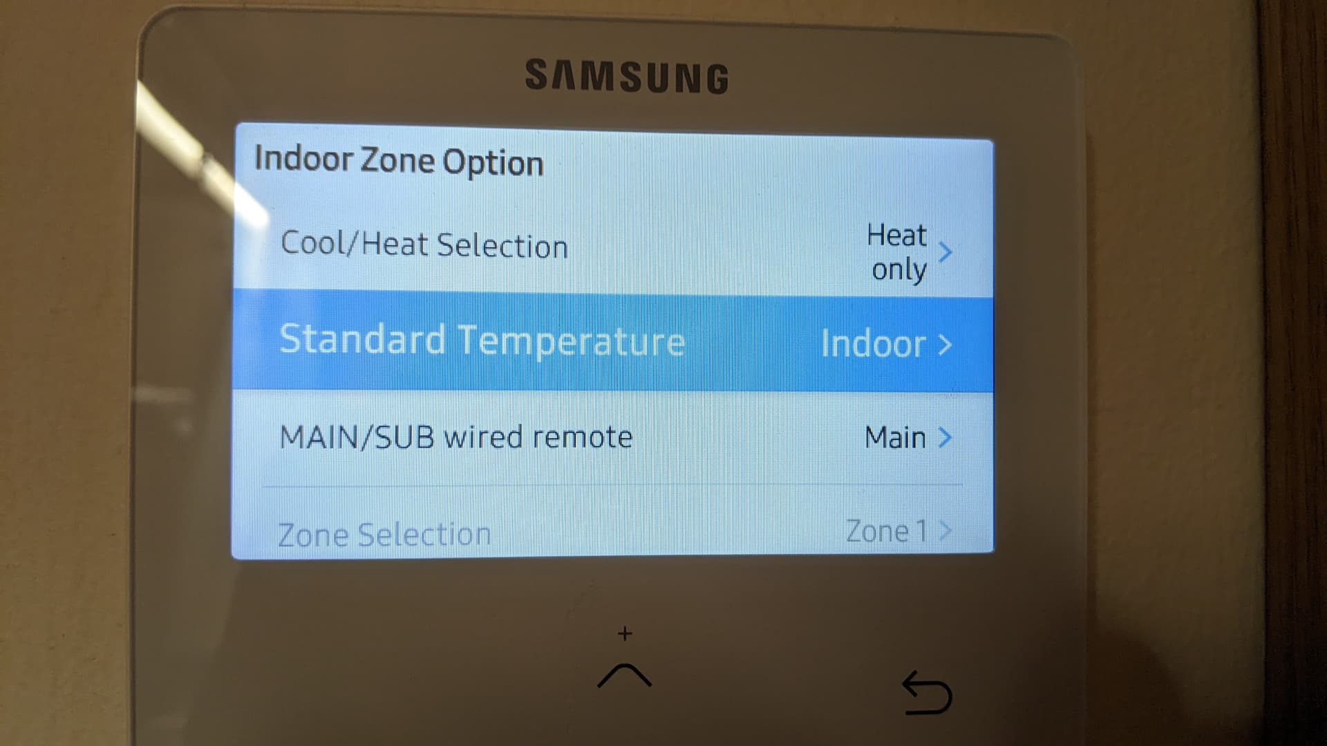
I use the Samsung controller which is located in my living space as the room thermostat. WC is used to set the flowT via water law and then the roomT is used to inform the unit when to switch on/off. I think using the Samsung controller rather than a third party thermostat gives the best results in terms of hysteresis etc. This is what Midsummer recommend in their Samsung quickstart guide.
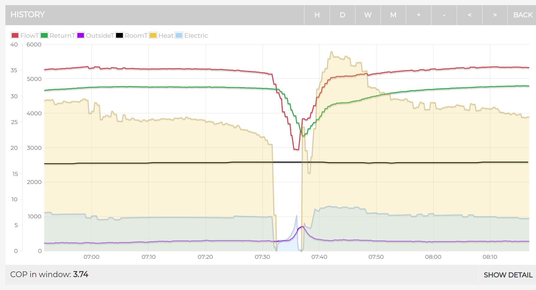
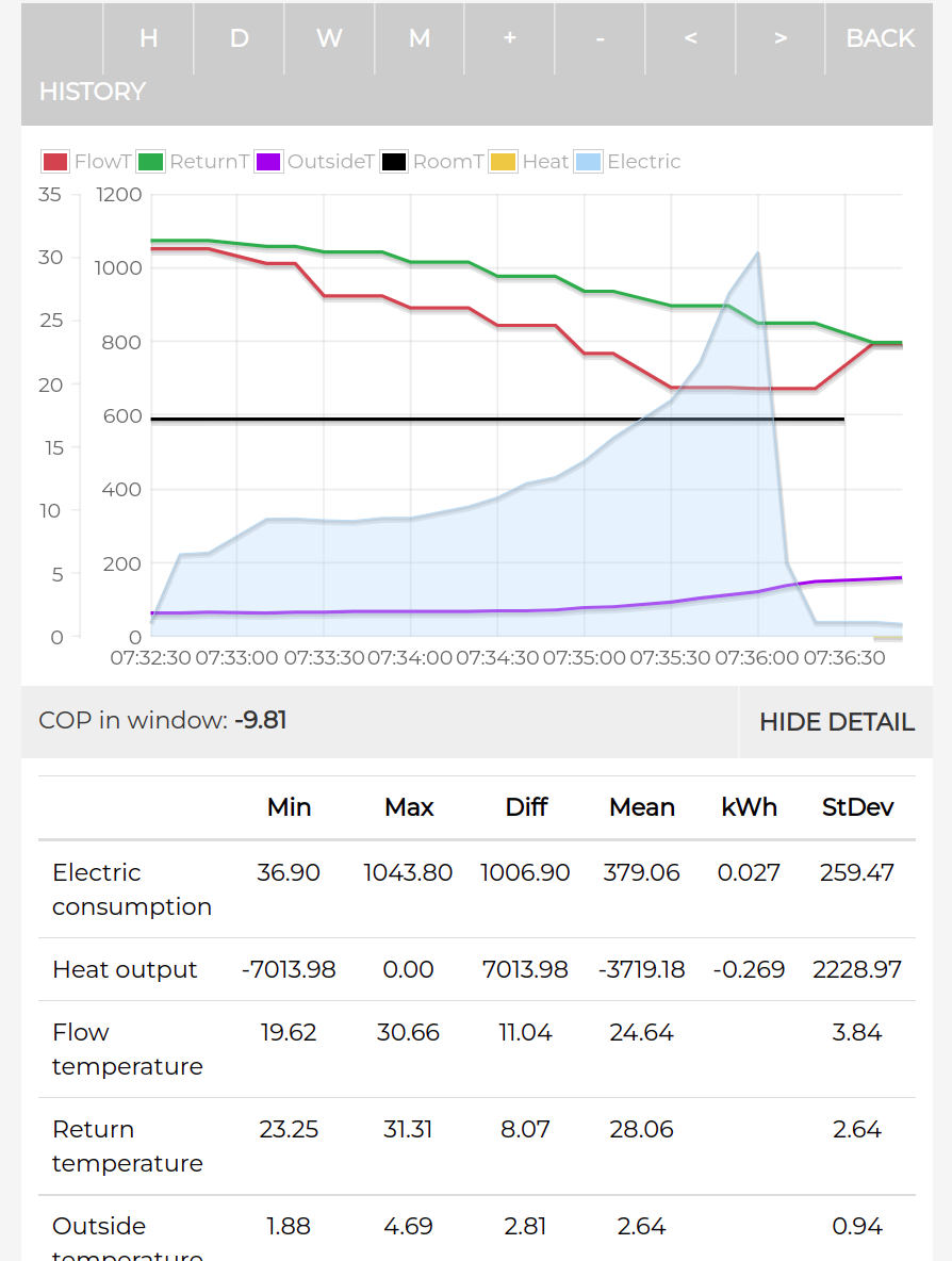
We can see that the electrical consumption was 0.027kW and the power peaked at 1kW, the defrost also extracted 0.27kWh of heat from the house. The defrost cycle lasted 4min.
Mine if a 5kW unit, a larger heat pump will require more energy to defrost because it’s physically larger i.e more ice to melt!
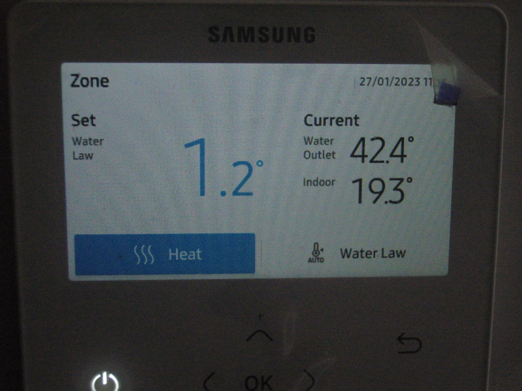
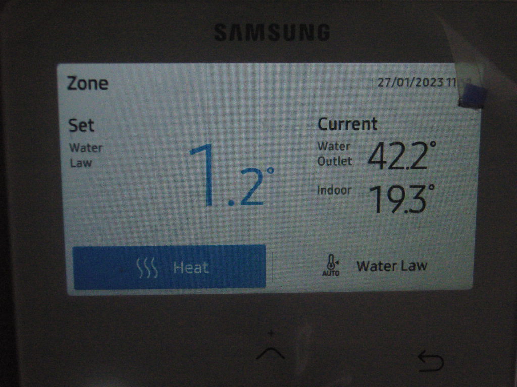
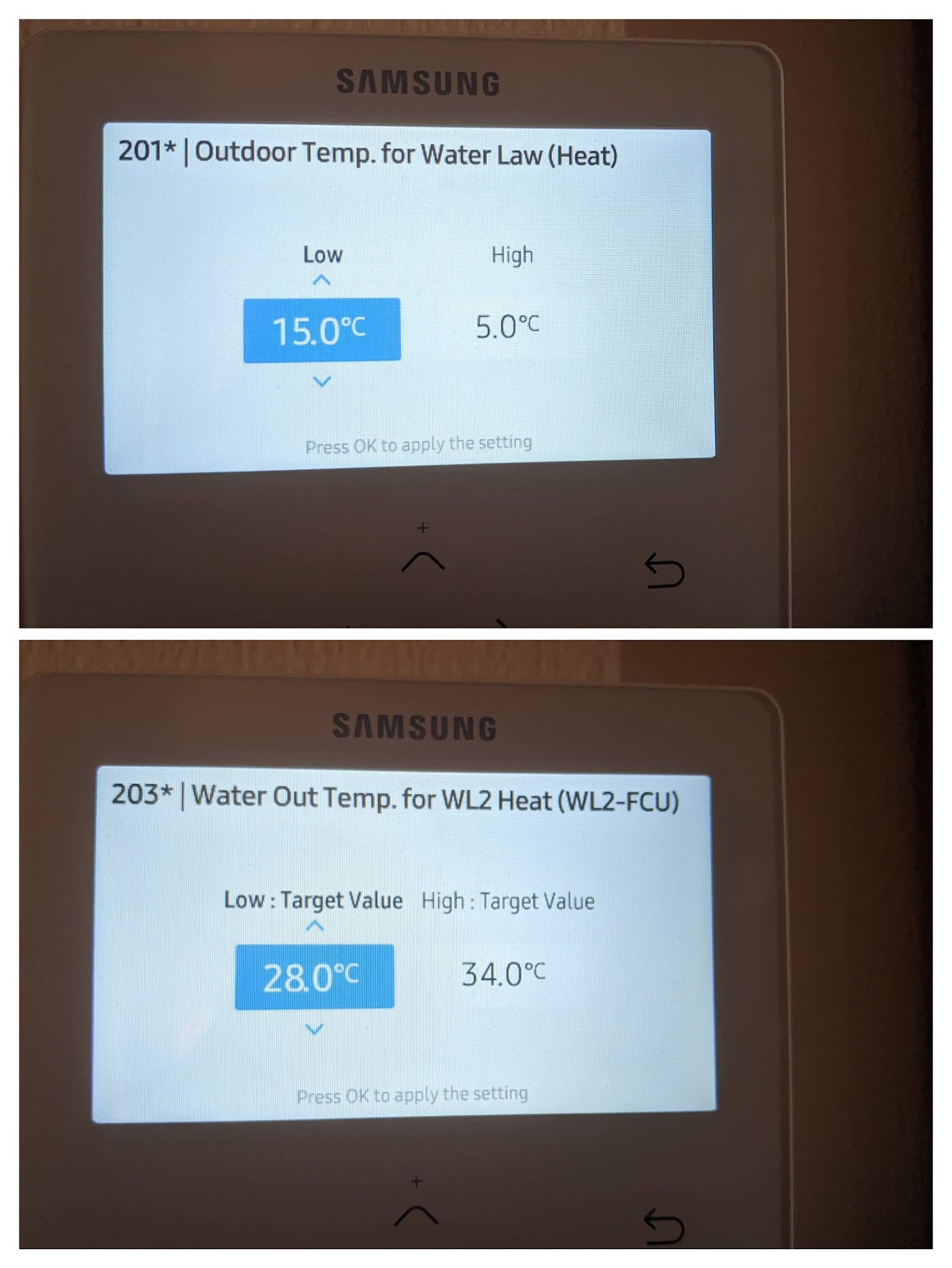
I’m not sure what you mean here, the WC is set on the water law field setting page. These are my WC settings, what are yours?
Interesting - never understand why sometimes it matches well and other not. Always amazes me that it takes ages to correct. So if one rises more than the other, it seems to get stuck at a differential for a while. I see differences in reaction times as well as absolute value differences.
De-icing power / Energy
My DE-icing consumption is larger than yours with the energy needed to convert ice at -8 C to steam over 50 cycles sometimes amounting to 2 Kwh.
With a care home for a neighbour , I must not, however, emit large quantities of Steam.
I will run the de-icing diagnostic during a cold night to separate de-icing consumption from cycling consumption.
The 201* are the settings used by the Weather compensation system graph.
Your values are again ,different, in my, much colder, climate.
That seems like quite a lot of energy, what do you mean by 50 cycles? -8C is quite extreme even for Scotland, at these very cold temperatures there’s less moisture in the air so defrosts will be less frequent than they are around 0C. The coldest I’ve seen is -5C, and I did indeed observe far less frequent defrosts at this temperature:
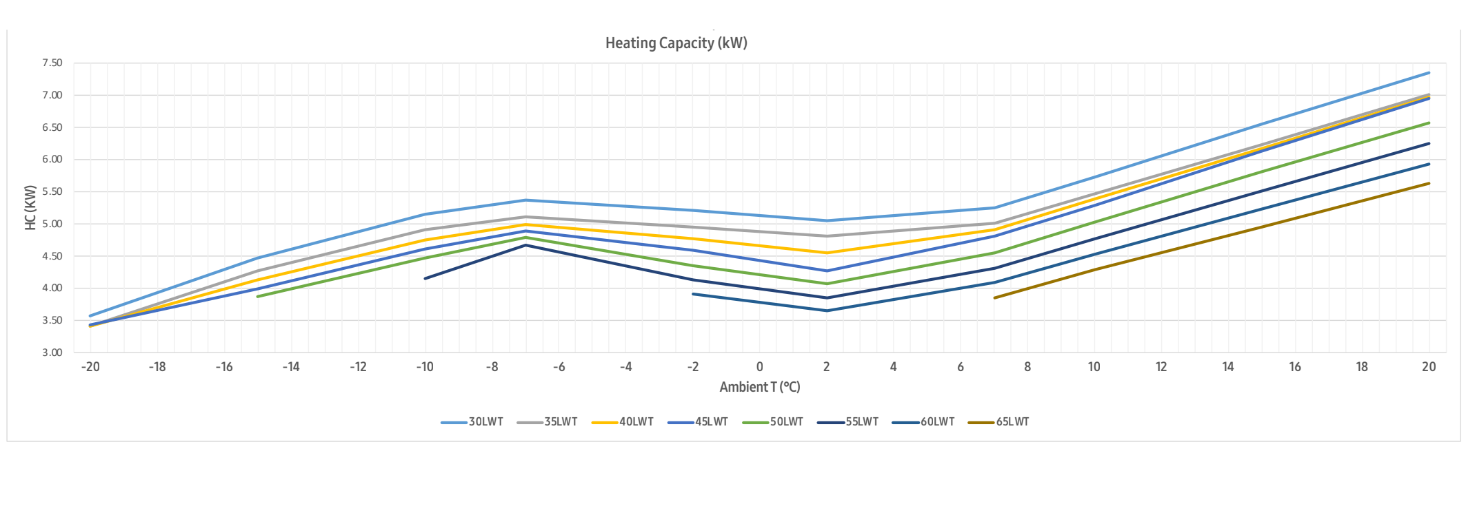
The Samsung datasheet shows a higher heating capacity at -8C then 2C because of the less frequent defrosts due to less moisture and less icing. This screenshot is for a 5kW unit but the same physics will apply to larger units.
When finished the Diagnostic returns the following parameters:
1 040 Outdoor Temperature 11 C.
2 Discharge Sensor 54 C.
3 EVA Sensor 29 C
4 Inlet Water flow Temp 35 C.
5 Outlet Water Temp 37 C
6 Condenser Sensor 3 C
7 Current 3.9 Amps
8 Fan RPM 76 Rpm
9 Discharge Sensor 71 C
10 EEV 152
11 Protection Comtrol = Heating , No Protective control , Up Limit
12 IPM Temp 25 C.
The DE-icing Diagnostic T3 was then run for 3 minutes.
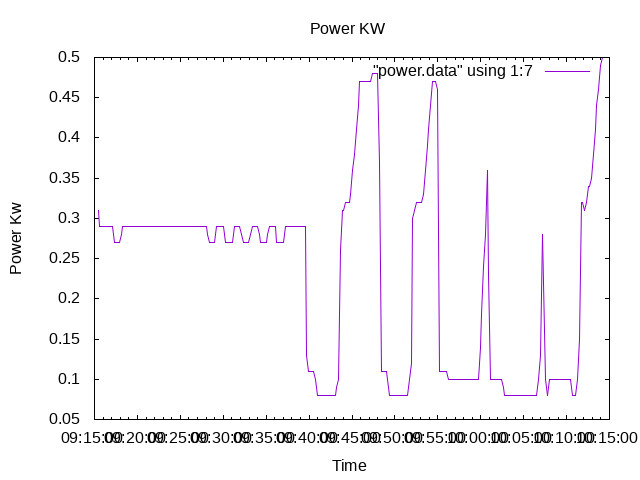
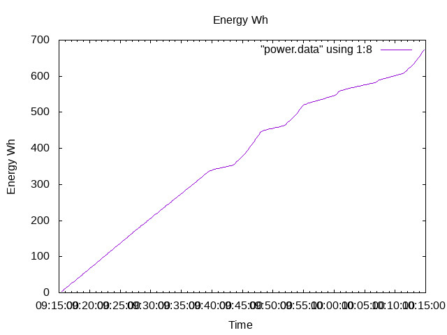
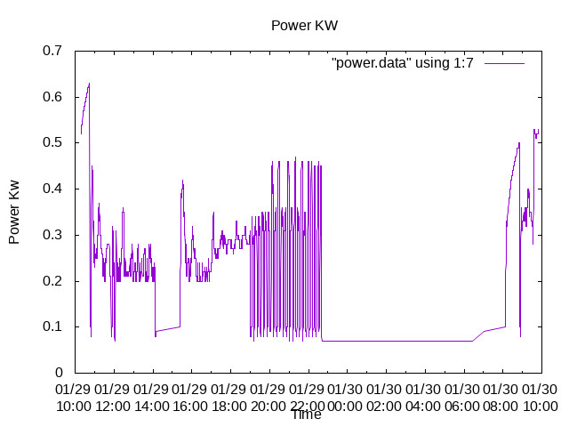
The Power used during both tests is shown in
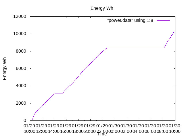
The Energy consummated in both tests is
The Energy consumed on the Heating Diagnostic was 96 Wh.
The Energy consumed on the De-icing Diagnostic was 55 Wh.
The Heating diagnostic was run for 6 mins while the De-icing Diagnostic was run for 3 mins.
Conclusions
1 The Heat Pump is working well.
2 De-icing is working well.
3 Heating consumes 96 over 6 mins = 0.266 W during these test.
4 De-icing consumes 55 over three minutes = 0.3 W.
Could someone else confirm these tests on other Samsung’s?
ian
I think what you’re seeing is actually water vapour a few degrees above ambient temperature, not steam at 100° C. Most of the ice will melt and drain away as water, with a small quantity evaporating as water vapour.
Exactly, commonly called “clouds”. Steam is invisible, if you look at the spout of a boiling kettle, steam is what comes out. Look carefully and you see nothing immediately. A centimetre or so later, it has cooled and condensed into minute droplets of water, and that’s when it becomes visible.
I may be seeing Water Vapour , it does not however , obscure the fact that de-icing, whatever it’s final form consumes about 100 Wh of Electricity during each cycle.
With a maximum consumption , between 4 am and 8 am , of 2 Kwh, this would represent 2000/100 = 20 Oscillations . I have , I think, observed some 20…50 such de-icing cycles.
My further point , is , Run the Samsung Diagnostic , t3
The Diagnostic limits the number of variables, and allows comparisons to be made between different Samsung’s.
What is your De-icing consumption per cycle?
How many De-icing cycles do you see on cold nights?
I began , almost nine months ago , as a green , loud , proponent of Heat Pumps.
After nine months I am no longer a proponent of Heat Pumps.
I have spent many of the last nine months face saving!
I could not lose face face by admitting that my decision to install a heat pump was a mistake.
The endless E-mails and Telephone calls to the “Regulators”, the MCS ,NIC and the RECC, have resulted in the "Reluctantly "provided advice that I seek legal advice…
MY propensity for self deception is well expressed by the bard
“O, wad some Power the giftie gie us To see oursels as others see us! It wad frae monie a blunder free us, An’ foolish notion.”
This doesn’t seem to be particularly excessive, and is about the same as other systems I’ve looked at. 50 Wh is perhaps more typical, but still in the same ball park.
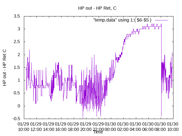
20 de-icing cycles over 4 hours is more frequent than I would expect though; I rarely see more than 2 per hour. You can count de-icing cycles by looking at where the flow temperature goes below return temperature.
2 kWh over 4 hours is an average consumption of 500 W, which seems pretty reasonable if it’s heating your home.