Inaccuracy of RPICT3T1 and CT sensor sct-013-000 compared to electricity meter reading

Hi,
I am not electronics specialist so read with caution please.
I have purchased RPICT3T1 RPICT3T1 - lechacal (faq zttp://lechacal.com/wiki/index.php?title=Frequently_Asked ) and sct-013-000 in hopes to measure my whole house electricity usage and once I know its accuracy by comparing to electricity meter, place it on the circuit used by air heat pump system and see what is my percentage is actually used by heating system and at what times.
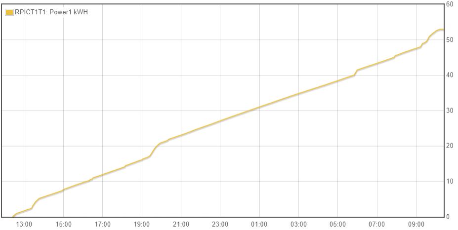
I placed sct-013-000 on my house main incoming live cable before it goes in the circuit breaker, inside AC distribution box (outer casing was touching another live cable that was connected at the same breaker input). But my readings in kWh are way off the electricity meter one, emoncms with sct-013-000 = 53 kwh and electricity meter = 8kwh for ~20 hours. Attaching kWh and Power graphs screenshots.


Before installing sct-013-00 on main incoming live cable I did some tests on smaller appliances using plugin watt meter “MODEL 2000MU”, attached is the manual, not sure about its accuracy but at least rough idea. From what I see is that watt meter VA value is close to RPICT3T1 value.

Tests
Computer, Watt meter readings: 53VA 46W 0.22A 0.05kWh RPICT3T1 reading: 59.71W 0.06kWh
Hoover at medium setting, Watt meter readings: 1679VA 1062W 7.17A , RPICT3T1 reading: 1722W
Hoover at max setting, Watt meter readings: 2003VA 1903W 8.8A , RPICT3T1 reading: 2056W

My Setup
I connected RPICT3T1 to old “raspberry pi b” serial pins and installed emoncms using zttps://raw.githubusercontent.com/openenergymonitor/EmonScripts/stable/install/init.sh on it and it is capable of reading values from serial port after editing emonhub config by replacing node 11 with

[[11]]
   nodename = RPICT1T1
   firmware = RPICT3T1_V1_1.ino
   hardware = RPICT3T1
   [[[rx]]]
       names = Power1,Power2,Power3,Temperature
       datacode = 0
       scales = 1,1,1,1
       units = W,W,W,C

and replacing [[RFM2Pi]] interface with

[[SerialDirect]]
     Type = EmonHubSerialInterfacer
      [[[init_settings]]]
           com_port = /dev/ttyAMA0      # or /dev/ttyAMA0 or/dev/ttyACM0 etc
           com_baud = 38400              # to match the baud of the connected device
      [[[runtimesettings]]]
           pubchannels = ToEmonCMS,

Inputs were created automatically just needed to create the “process list setup” entries, “log to feed” and “Power to kWh”
RPICT3T1 is sending its information every 2 secconds

2022-09-22 10:35:49,217 INFO     MainThread EmonHub emonHub (emon-pi variant) v2.2.6
2022-09-22 10:35:49,231 INFO     MainThread Opening hub...
2022-09-22 10:38:23,781 INFO     MainThread Logging level set to DEBUG
2022-09-22 10:38:23,792 INFO     MainThread Setting emoncmsorg senddata: 1
2022-09-22 10:38:23,794 INFO     MainThread Setting emoncmsorg sendstatus: 1
2022-09-23 00:15:29,819 DEBUG    SerialDirect 1416 NEW FRAME : 11 59.51 7.13 7.87
2022-09-23 00:15:29,824 DEBUG    SerialDirect 1416 Timestamp : 1663888529.818701
2022-09-23 00:15:29,826 DEBUG    SerialDirect 1416 From Node : 11
2022-09-23 00:15:29,829 DEBUG    SerialDirect 1416    Values : [59.51, 7.13, 7.87]
2022-09-23 00:15:29,832 DEBUG    SerialDirect 1416 Sent to channel(start)' : ToEmonCMS
2022-09-23 00:15:29,834 DEBUG    SerialDirect 1416 Sent to channel(end)' : ToEmonCMS
2022-09-23 00:15:29,956 DEBUG    MQTT       Publishing: emon/RPICT1T1/Power1 59.51
2022-09-23 00:15:29,961 DEBUG    MQTT       Publishing: emon/RPICT1T1/Power2 7.13
2022-09-23 00:15:29,966 DEBUG    MQTT       Publishing: emon/RPICT1T1/Power3 7.87
2022-09-23 00:15:29,972 INFO     MQTT       Publishing 'node' formatted msg
2022-09-23 00:15:29,975 DEBUG    MQTT       Publishing: emonhub/rx/11/values 59.51,7.13,7.87
2022-09-23 00:15:31,778 DEBUG    SerialDirect 1417 NEW FRAME : 11 59.55 7.63 7.64

Calibrating clamp output:
• Calibration VCAL ICAL PHASECAL - lechacal
• Formula for calculating kcal value “newICAL = ICAL*Ireal/Imes”
• RPICT3T1 “kcal = 26.67 1. 1. 26.67 1. 1. 1. 26.67”
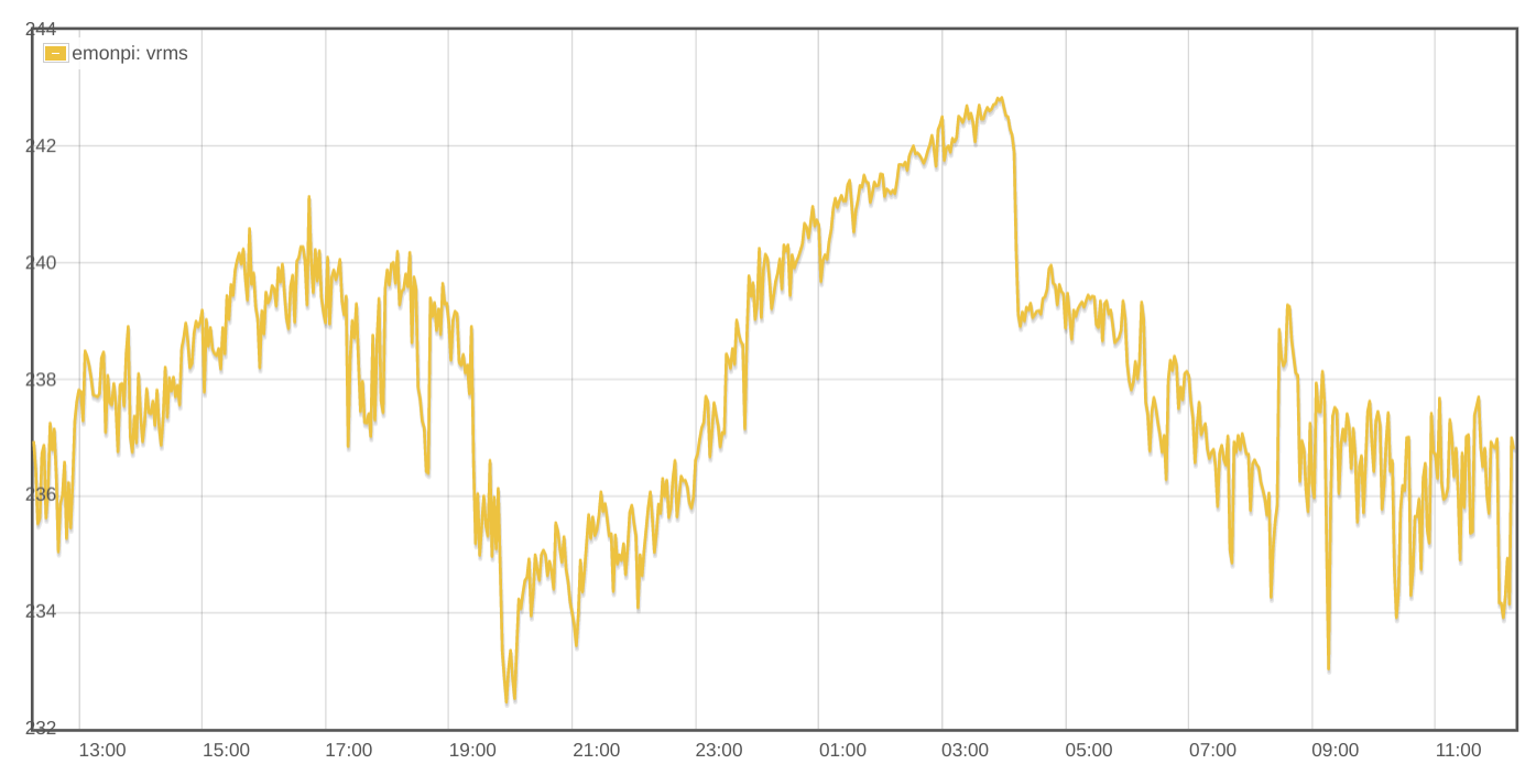
• Output is in watts and there is a constant voltage variable of 240v in config file of RPICT3T1(voltage on my watt meter is ranging from 232-241 when on load), e.g. 1070.30 6.91 7.17 which shows that ct1 shows 1070.3 W

Questions:

  1. What information should I provide in order to better understand the problem?
  2. Is it the problem with rpict3t1 and sct-013-000 providing inaccurate information or wrong emoncms configuration of input feeds?
  3. Am I correct in thinking that VA value of my watt meter is the measurement value that my electricity meter is using to calculate kwh, or is it watt on my watt meter?
  4. How accurate should VA be to my house electricity meter in kwh, providing that rpict3t1 uses estimated power due to fixed 240 voltage, rough estimates ~80-90% accuracy?
  5. Should I be using “kWh accumulator” instead of “Power to kWh”?

P.S. Had to replace http urls to zttp.

Thank you in advance

Hello Oleg,

I’ve bumped your user account level up a notch. You should be able to upload now.

Regards,

Bill

Hello Bill,
Thank you for doing that!
I wasn’t able to upload pdf but I converted it to image and uploaded.

I haven’t yet waded through all the information in your post, however I’ll try to outline a few points that might help you to understand the various quantities you’re measuring. You’ll find quite a lot of basic theory in the ‘Learn’ section here.

Firstly, your RPICT3T1 only measures current. Current has a complicated relationship with power. The power for a given current varies according to the voltage at the time (and I have no experience of Ireland, but where I am, it varies quite a lot according to what everyone else in the locality and indeed the country is using) and equally if not more importantly, the appliance or appliances in use at the time.
This leads to the answer to question 3: No, it’s neither the VA reading nor the kWh reading; and to question 4: nobody can say that - it depends on what is using the electricity.

VA is the result of multiplying the average voltage (Volts) by the average current (Amps). If you have something like a microwave oven on standby (so it’s only the clock that’s powered), the voltage could be 240, the current could be 20 mA, so the Apparent Power is 4.8 VA. But it won’t be 4.8 W, if you measure the real or active power, that would be something like 1 W or even less. If you do the same for an electric kettle, it will draw say 6.25 A and the real and apparent powers will both be 1.5 kW. The apparent power is never less than real power.

But I think the fundamental problem lies with the calibration of your RPICT3T1. The web page lists 5 current transformers as being suitable, yet they require different calibration in the software and possibly different components on the board:
The SCT-013-000 ratio is 100 A : 50 mA
The SCT-019 has 13 variants from 200 A : 33 mA (current output) to 5A : 0.33V to 200A : 0.33 V (voltage output)
The SCT-006 is 20 A : 25 mA
The SCT-024 is 400A : 100mA
The SCT-031is 600A : 100mA

Have you set the correct calibration? I don’t have the board in question, so I can’t tell you what you need to do. I would be surprised if it’s not in the documentation somewhere. When you get this right, I think your numbers will come a lot closer to you supplier’s meter readings. But, as I implied above, your will never get an exact match because the two are reading different quantities: the supplier’s meter is measuring real power relatively accurately, your Pi is making a guess at what the power might be provided you guess the correct representative voltage and power factor (the ratio real power / apparent power) for your whole house for whatever period of time you’re considering. With careful calibration over a period of time (weeks, probably), you should get the energy (kWh) to match to better than 5%, and probably much better. But short-term, you’ll find the values drift apart in one or the other direction and then come back together again.

When you get those fundamental things right, then all the rest will make a lot more sense.

Thank you for the detailed and very informative reply Robert. I was confused trying to read “learn it” after spending a few days online reading/watching many different articles and not getting the idea of what information electricity meter uses to get the result. “AC power theory “ is the one I need to look at. I am sure I misunderstood something or made mistakes in this post.

My main idea was to use “raspberry pi b” that I had laying around when I need to do measurements for a few days, I wasn’t planning on running it non-stop for months, maybe during winter. I thought it will save me going out every day outside at exact time in order to take a meter reading whenever I was changing heating schedule and temperatures to find optimal time, temp and decide when to do the changes using gathered data.

Apologies for not providing full model, it is “RPICT3T1 v2.4 30A sct-013-000”. In faq No 12 Frequently Asked - lechacal it mentions that “Every board is sold fixed for a given sensor and given range of reading.” and has specific config file with calibration. I have downloaded it and applied as per instructions. The readings in previous post were done with the config file in place. I have “yhdc sct-013-000 100A” current sensor.

Config file details


key: HXQO

model: RPICT3T1

version: 2.4

summary: 30A SCT-013-000

firmware: RPICT3T1_v3.3

hardware:

CT1 to CT3:

Burden Resistor: 75Ί

Range: 30A

Sensor: SCT-013-000

ICAL: 26.67

Config file used by RPICT3T1


[main]

format = 3

nodeid = 11

polling = 2000

kcal = 26.67 1. 1. 26.67 1. 1. 1. 26.67

phasecal = 0

vest = 240.00

xpFREQ = 50

Ncycle = 20

debug = 0

Below are some key things I took a note of from your reply

  • Apparent power (VA) = V*I (volts * current)
  • Estimated power provided by RPICT3T1 is probably based on static voltage, current read using sct-013-000 and possibly static power factor
  • Real/active power(W)= V*I * power factor(W/VA) is used by electricity meter
  • Readings will never match exactly due to power factor difference and voltage fluctuations.

Further questions:

    • Assuming my watt meter is quite accurate should I use WATT reading when calibrating RPICT3T1 and what devices should I connect to watt meter to calibrate best, I assume resistive load like kettle, toaster or heatgun around 2kw where apparent and real load are nearly the same?
    • RPICT3T1 ICAL calibration lists the formula “newICAL = ICAL*Ireal/Imes” and message below “Ireal being the current measured by the trusted multimeter. Imes being the current measured initially by the RPICT board.” but the output is in watts so I assume I have to use existing ICAL value “26.67” watt meter WATT reading/measured watt value provided over serial by RPICT3T1. Would you think it is correct?
    • Providing ac current test measurements outside ac distribution board below, my newICAL= 26.67*1903/2001= 25.36382308845577 , am I correct?
      • Hoover max setting, watt meter readings: 1903W 2001VA 49.9HZ 0.95PF RPICT3T1 reading: 2056

Key things:
Yes, those are indeed key. We know the RPICT3T1 uses a fixed voltage that you tell it (“vest”), it must assume a power factor - probably 1.0

That’s not quite true. Notice when I explained VA, I wrote “average current” and “average voltage”. Your meter does it differently: The old mechanical Ferraris meter multiplied the current and a current derived from the voltage in real time to drive the spinning disc around. A modern electronic meter does exactly what the emonTx and emonPi does, it takes a a sample of current and a sample of voltage and multiplies those to get the instantaneous power, repeats that process several thousand times per second, and averages the result to give power, or adds up all the sample powers and multiplies by time to give energy (kWh). At the same time from the same samples, it will calculate the average voltage and current and calculate apparent power, hence the power factor. So power factor is the result of knowing real and apparent powers.

Further questions:
1. Yes, you must use something like a kettle or toaster. Even the heat gun will have a fan which will give it a slightly inductive power factor.
2. I would ignore that, and first check the voltage and adjust “vest” accordingly, then measure the power and adjust ICAL based on what you read on both the RPICT and your power meter.
3. The SCT-013-000 has a claimed accuracy of Âą3% over the range 10% - 120% rated current, i.e. from 10 A to 120 A. Outside that range, it is not specified at all. So you must not expect accurate readings below 10 A, and our experience is indeed that, though the amplitude error (which is all that concerns you) remains quite small to as low as I’m able to measure it, which is around ½A. Until you’ve got a reasonably accurate calibration at the maximum current/power that you can measure, there’s little point in checking anywhere else. The point of calibration is to adjust your RPICT to the individual c.t. that you’re using so that it’s as accurate as possible, given all the other limitations. It looks as if you’re within about 5% already, with pure resistive loads (kettle, etc) you should be able to improve on that provided your supply voltage remains reasonably constant. This is what my voltage looks like over the last 24 hours:

You can draw your own conclusions about accuracy if you’re not measuring the voltage. :face_with_raised_eyebrow:

Or even 563mA, for an Apparent Power of 135VA and a real power of ⅓ Watt.

I’ve attached 3 mains cycles worth of voltage and current readings in a CSV text file in case @vecnar wants to try his hand at making a power meter inside a spreadsheet. These were sampled at 8KSPS, so every 125 usecs you get a new V,I pair.

If you apply the maths Robert describes above, you should get something like:

which is also what the meter was reporting.
m0ch06b.txt (10.0 KB)

1 Like

Thank you for your reply Robert and sorry for late reply, I am very slow at trying to understand/learn new things.
I think I am getting closer to understanding how real power is calculated and see the need for voltage sensor.

Lechacal wiki page http://lechacal.com/wiki/index.php?title=RPICT_Fundamentals has the formulas and your explanations helped me to understand the difference between apparent power and real power, or so I think. I didn’t want to copy and paste all the page here.

To summarise my understanding of my current setup:

I will not achieve accurate reading without “AC voltage sensor” and “Current sensor” that connect to card which does all the calculations thousand times a second.

Providing my house current load most of the time stays under 10A and max at 50A according to sct-013-000 100a (in reality I think it is much lower and doesn’t go above 30A), sct-013-000 100A is not a good option if I would want accurate results.

Can’t think of any use for current setup for electricity monitoring as electricity monitors/meters should provide accurate results/data to make decisions.

Questions:

  1. I assume power mentioned above is the “real power” that is used by electricity meter? This is just to confirm my understanding.

  2. I also have sct-013 30a/1v meter that I acquired by mistake, is there any way of adding/integrating some type of voltage sensor into my existing setup, I assume not and probably to achieve what I want I would need to purchase single board that has connection for current sensor and voltage sensor like RPICT3V1 and AC->AC voltage sensor?

@dBC thank you for providing information and showing spreadsheet with the graph, didn’t know you can do it so well in excel.

The fundamental fact is that the characteristics of the load, the voltage, the current and the powers - both real and apparent - are related to one another by relatively simple formulas. You must know two of the three - the load, voltage and current - to calculate the powers. For a whole house, you can never know the characteristics of the load because it changes from minute to minute, so you need both current and voltage. Current alone would be enough if the voltage was fixed and constant, but in the real world that does not happen.

This leads to…

Yes, that is correct.

This is most likely correct - but of course only you know what you will have switched on at any time and what current each appliance will draw. It will almost certainly be the case that you will never use everything at the same time - that’s all that anyone else can say.

This I question. You’ve already touched upon it earlier - you need to go and look at the meter regularly. If you use you RPICT and send the results to a computer somewhere that keeps a minute-by-minute record, and you know roughly what power each appliance takes and when you used it, you can very easily build up a picture of where your costs are arising. It won’t be totally accurate, as I’ve explained, but it will give a broad understanding.

Yes, that’s correct.

Without making modifications to both the hardware and the software, you’re right, you cannot do it with what you have.
But you most probably could use the SCT-013-030 provided that your maximum current does not exceed 33 A (110% of rated current). You would need to remove any burden resistor needed in the RPICT, because the SCT-013-030 already has a burden resistor inside, which is what makes its output a voltage rather than a current like the SCT-013-000. 1 V rms out, or 1.1 V if you go 10% over the maximum rated current, gives a peak-to-peak voltage swing that is close enough to 3.3 V (or even 4.096 V) to not warrant changing anything; instead you adjust the calibration to correct the values.

I see the RPICT page mentions a ZMPT module. Do not buy the ZMPT101B module from a third party supplier - it is useless for real power measurement, it includes a filter that introduces a massive phase error, which wreaks havoc with the real power calculations. The Lechcal module clearly does not have that filter, so it will be fine.

I just realised that screenshot might lead you to believe there are only about 30 lines in the spreadsheet. There are actually 480 entries to make up the full 3 line cycles… I just screenshot the top bits that show the calculation results.

Thank you Robert for all the help and advise.

I will take a note of the above.

Sorry for not using correct terminology.

Good to know that I can reuse sct-013-030, if I manage to find and desolder burden resistor on rpict3v1 or rpict7v1.
I will be buying ac/ac adaptor as I will have to be near ac socket to power raspberry pi but thanks for mentioning to stay away from ZMPT101B module from other suppliers.

@dBC Thank you for pointing that out

Just one thought, I have previously used a pulse sensor to calibrate my CT based readings observed over a period of time. By applying a correction factor on the Input process, I have been able to adjust the totals from the CT to be within a very small margin of error from the pulse sensor (i.e. the meter reading).

There is still possibly a variable error depending on the power drawn, so instantaneous readings will possibly have more error at different loads, but I’d suggest this is the best way to calibrate your overall readings.

This very definitely happens, especially with real power measurements - I have recorded it. Its principal contributor is the variation in phase error, so it’s likely to be less of a problem if only current is being measured.

Indeed - but “overall” means means over quite a long period - weeks rather than hours or days.

I added this caveat just for you :slight_smile:

No, the curves pretty well match over a period of a few hours from the data I have. I think you get to a point where rounding takes over when scaling the input process for the CT readings so you can only get it to a certain degree of accuracy. The error also (surprisingly) doesn’t appear to grow over time so the over reading and under reading seem to balance out (if you get the right scale figure).

Current calibration figure image

This got the error to less than 0.5%. Over different periods of time the error was pretty consistent.

It is most clearly shown in the Octopus (agile) App where you can add your (CT) reading value and the reported meter readings - it was where I first noticed the error manifesting itself and decided to try and calibrate against the pulse sensor. Of course the Meter readings and pulse readings should match if the pulse sensor is working correctly.

I’ve not checked this recently as I have had major issues with my dumb meters which now seem fixed, so I’ll look at it again when I have some time.

Yes - there are things I do weekly that make a discernible difference. If everything you do is constant hour to hour, then a 1-hour average or a few hours average, will be good. It will depend on your lifestyle.