Hello diybms community,
I am seeking help identifying why my build is not working. It is my first time building a pack with diybms and I’m hoping I’m just missing something simple because I’m a newB!
I am building a 7S arrangement, with version 4.5 balancing modules (57bf3f3) and version 4.6 main board (be885e1). When it starts up it reports software version d052e574 (2 Jan 2025).
At the moment I have just one balancing module and the main board hooked up in the serial loop. Is that an acceptable configuration for discovering the first module (don’t need them all)?
I have the TX port on the control board connected to the RX port on the balancing module by way of a straight-through JST cable arrangement, so that pin-1 of the TX port on the controller is connected to pin-1 of the RX port on the balancer. Then the return is the same (both cables are ‘straight through’ type).
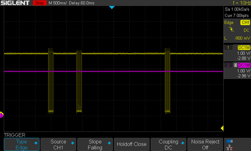
I have a scope attached to pin 1 of RX on the balancing module (yellow trace) and pin 2 of TX on the balancing module (pink trace). It looks to me like there is data coming out of the controller but no data coming out of the module. The controller continually displays “waiting for modules”.
I programmed the module using an updi2jtag programmer that I built out of an Arduino and the output from the programming session indicates that I successfully flashed them. When the module powers on it flashes LED D4 three times - does this indicate the correct code is running? I flashed them with module_fw_V450_10K_ATtiny1624_450_e0_h0_l0.hex
The instructions linked in the git repo have a bunch of missing images now (they used to be there), and in the end I wasn’t sure what command to use to do the updi programming, so I used the verbose output of the Arduino IDE to get this command from an upload of Blink and them amended it for the new hex name. But are these fuse settings ok?
“/Users/myusername/Library/Arduino15/packages/DxCore/tools/avrdude/6.3.0-arduino17or18/bin/avrdude” “-C/Users/myusername/Library/Arduino15/packages/megaTinyCore/hardware/megaavr/2.6.10/avrdude.conf” -v -V -pattiny1624 -cjtag2updi -P/dev/cu.usbserial-10 -b115200 “-Ufuse0:w:0b00000000:m” “-Ufuse2:w:0x02:m” “-Ufuse5:w:0b11110111:m” “-Ufuse6:w:0x04:m” “-Ufuse7:w:0x00:m” “-Ufuse8:w:0x00:m” “-Uflash:w:/Users/myusername/Downloads/Compiled_Firmware_2025-03-30-15-36/Modules/HEX/module_fw_V450_10K_ATtiny1624_450_e0_h0_l0.hex:i”
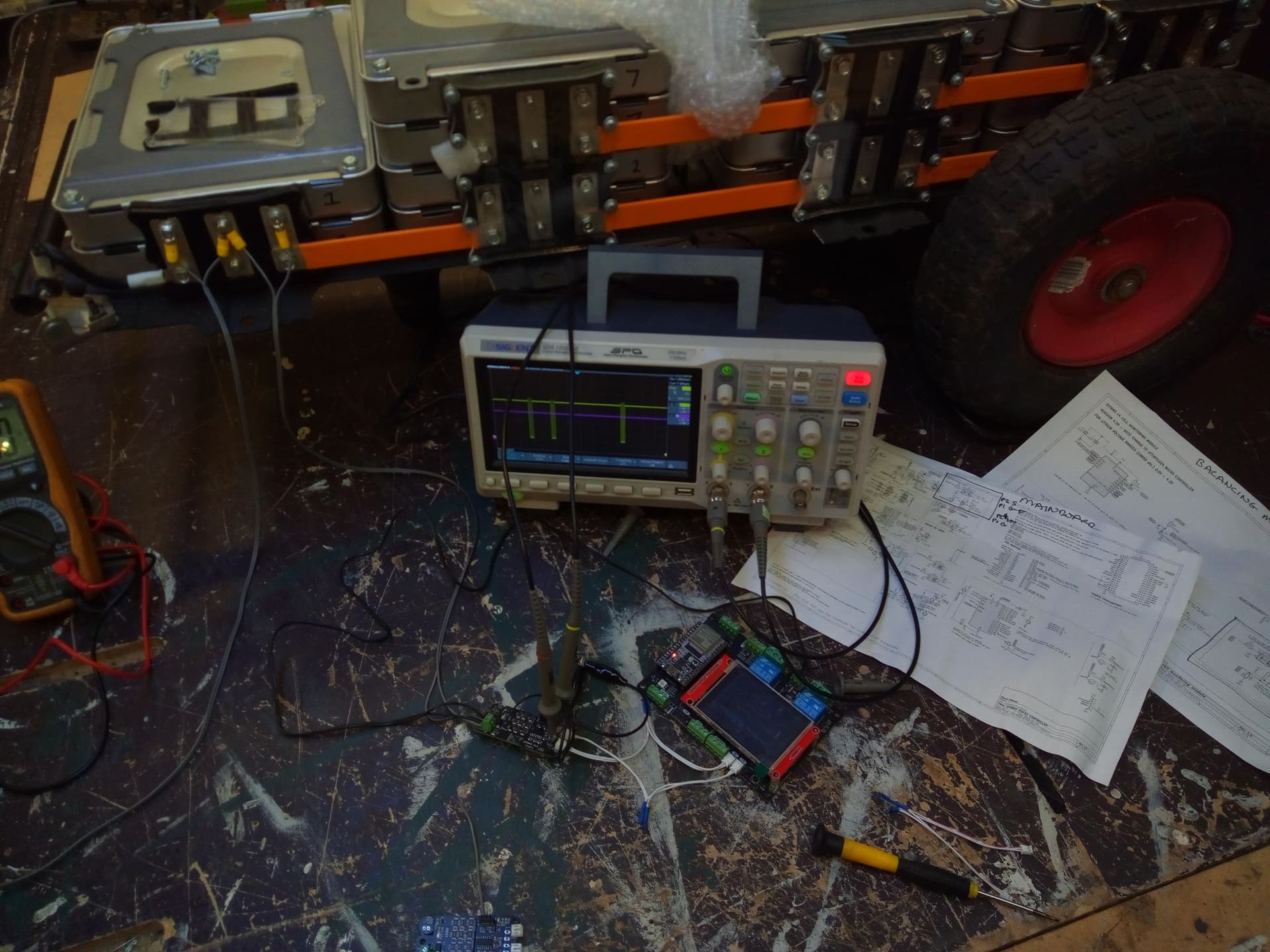
I will try and attach a scope grab and a photo of the setup. If attachments fail then the files can be viewed at the link below.
I also recorded this video the startup sequence where you can see the controller board send data on the scope (yellow trace):