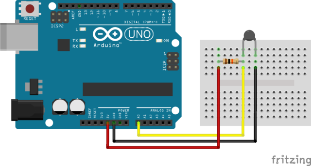
for anyone who wants to work with thermistors other resistance-type temperature sensors here the basic method of working with them. you should be able to work with all types of them.
the basic sketch
#include <math.h>
/// Example NTC 10K
/// Using the beta constant  -- less acurate ////
float Ro = 10, Beta =  3950; //Nominal resistance 10K @25C , Beta constant
float Rseries = 10;// Series resistor 10K
float To = 298.15; // Nominal Temperature @25C
//Example for PT1000
///// using Steinhart-Hart Coefficients more accurate //////

float A = 0.06501312861989986;  /// for the PT1000  use a 1k resistor
float B = -0.01161716353567784;
float C = 0.00005732815001133613;

void setup() {
  Serial.begin(115000);
}

void loop() {
  /*Read analog outputof NTC module,
   i.e the voltage across the thermistor */
  float Vi = analogRead(A0) * (5.0 / 1023.0);
  //Convert voltage measured to resistance value
  //All Resistance are in kilo ohms.
  float R = (Vi * Rseries) / (5 - Vi);
  float ohm = R*1000;

  /*Use R value in steinhart and hart equation
    Calculate temperature value in kelvin*/
  float T =  1 / ((1 / To) + ((log(R / Ro)) / Beta));
  float T_SH = 1 / (A + (B * log(ohm)) +  (C * ( log(ohm) * log(ohm) * log(ohm))));
  float Tc = T - 273.15; // Converting kelvin to celsius
  float Tc_SH = T_SH - 273.15;
  float Tf = Tc * 9.0 / 5.0 + 32.0; // Converting celsius to Fahrenheit
  float Tf_SH = Tc_SH * 9.0 / 5.0 + 32.0;
  Serial.print("ohms = "); Serial.println(ohm);
  Serial.print("kilo ohms = "); Serial.println(R);
  Serial.println("Beta Constant");
  Serial.println((String)"Temperature in celsius    :" + Tc + "°C");
  Serial.println((String)"Temperature in Fahrenheit :" + Tf + "°F");
  Serial.println ("Steinhart-Hart Coefficients");
  Serial.println((String)"Temperature in celsius    :" + Tc_SH + "°C");
  Serial.println((String)"Temperature in Fahrenheit :" + Tf_SH + "°F");
  Serial.println(" ");
  delay(1000);
}
now if you know your sensor type you can look up the resistant table or the beta constant
example for the NTC 10k B=3950 for the beta constant at 25C or the resistance :
at 0C the resistance is 33620, at 60C it is 2486 and at 120C it is 407
for the PT1000
at 0C the resistance is 1000 at 60C it is 1232 and at 120C it is 1460
simply enter those numbers into one of calculators
for an unknown thermistor simply measure its resistance at 3 different temperatures with in your working range. ie 0C 60C and 100C if the thermistor is a high temperature one then say 0c 100C and 200C
and use a resistor that is suitable for your sensor if at 25c it 10k use a 10k. if the sensor works in the 1k range uses a 1 k and if lower use a lower one
the above sketch displays the ohms when testing just it tosee if it has same ohm reading as what the sensor gives directly using multimeter
here another sketch based on ads115 i2c analog it abit nicer to use as it 16bit and determines its own voltage
#include <math.h>
// β coefficients for NTC 10 3950
float Ro = 10, B = 3950; //Nominal resistance 50K, Beta constant
float Rseries = 10;// Series resistor 10K
float To = 298.15; // Nominal Temperature
float Vo = 3.29; /// voltage of the source
///β coefficients for PT1000
float Ro2 = 1.10201, B2 = -316.44;
float R_SH = 1;
//Steinhart-Hart model coefficients for PT1000
float A = 0.06501312861989986;
float b = -0.01161716353567784;
float C = 0.00005732815001133613;
float Tc1 =0; // NTC 10 sensors 1-4
float Tc2 =0;
float Tc3 =0;
float Tc4 =0;
int sample = 15;
#include "ADS1X15.h"
ADS1115 ADS(0x48);
void setup() {
Serial.begin(115200);
Serial.println(__FILE__);
Serial.print("ADS1X15_LIB_VERSION: ");
Serial.println(ADS1X15_LIB_VERSION);
ADS.begin();
}
void loop()
{
THERMO();
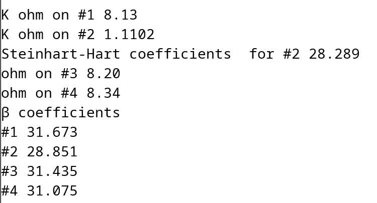
Serial.println("β coefficients");
Serial.print("#1 "); Serial.println( Tc1, 3 );
Serial.print("#2 ");Serial.println( Tc2, 3 );
Serial.print("#3 ");Serial.println( Tc3, 3 );
Serial.print("#4 ");Serial.println( Tc4, 3 );
Serial.println(" ");
delay(1000);
Tc1 = 0; // resets thermo sampling
Tc2 = 0;
Tc3 = 0;
Tc4 = 0;
}
void THERMO() {
ADS.setGain(1);
float ohm1 =0;
float ohm2 =0;
float ohm3 =0;
float ohm4=0;
float T2 = 0;
for (int i = 0; i <= sample; i++) {
int16_t val_0 = ADS.readADC(0);
int16_t val_1 = ADS.readADC(1);
int16_t val_2 = ADS.readADC(2);
int16_t val_3 = ADS.readADC(3);
delay(50);
float f = ADS.toVoltage(1); // voltage factor
float f1=(val_0 * f);
float f2=(val_1 * f);
float f3=(val_2 * f);
float f4=(val_3 * f);
// Serial.println(f1, 4); //prints the voltage of f1
float Vi = f1;
//Convert voltage measured to resistance value
//All Resistance are in kilo ohms.
float R = (Vi * Rseries ) / (Vo - Vi); // - to increase + to decrease .1 resistance = .5c
//Serial.println(R);
/*Use R value in steinhart and hart equation
Calculate temperature value in kelvin*/
float T = 1 / ((1 / To) + ((log(R / Ro)) / B));
float TcA = T - 273.15; // Converting kelvin to Celsius
//float Tf = Tc * 9.0 / 5.0 + 32.0; // Converting Celsius to Fahrenheit
Tc1 = Tc1+TcA;
ohm1 =R;
/////////////
Vi = f2;
R = (Vi * R_SH ) / (Vo - Vi); // - to increase + to decrease .1 resistance = .5c
float TMP = R/R_SH;
T = 1 / ((1 / To) + ((log(R /Ro2)) / B2));
float TcB = T - 273.15; // Converting kelvin to celsius
Tc2 = Tc2+TcB;
T2 = (1 / (A + (b * log(R*1000)) + (C * ( log(R*1000) * log(R*1000) * log(R*1000))))-273.15 );
ohm2 =R;
//////////////
Vi = f3;
R = (Vi * Rseries ) / (Vo - Vi); // - to increase + to decrease .1 resistance = .5c
T = 1 / ((1 / To) + ((log(R / Ro)) / B));
float TcC = T - 273.15; // Converting kelvin to celsius
Tc3 = Tc3+TcC;
ohm3 =R;
Vi = f4;
R = (Vi * (Rseries )) / (Vo - Vi); // - to increase + to decrease .1 resistance = .5c
T = 1 / ((1 / To) + ((log(R / Ro)) / B));
float TcD = T - 273.15; // Converting kelvin to celsius
Tc4 = Tc4+TcD;
ohm4 =R;
}
Serial.print("K ohm on #1 "); Serial.println(ohm1);
Serial.print("K ohm on #2 "); Serial.println(ohm2, 4);
Serial.print("Steinhart-Hart coefficients for #2 ");
Serial.println(T2 ,3);
Serial.print("ohm on #3 "); Serial.println(ohm3);
Serial.print("ohm on #4 "); Serial.println(ohm4);
Tc1 = Tc1/sample;
Tc2 = Tc2/sample;
Tc3 = Tc3/sample;
Tc4 = Tc4/sample;
return;
}
// -- END OF FILE --
from random trials it would seam that NTC are more accurate at lower temperatures and the PT are more accurate at higher temperature. and the using Steinhart-Hart coefficients gives a better temperature accuracy over all …
For anyone reading the above posts, it is worth pointing out that PT100 & PT1000 Platinum Resistance Thermometers (which are referred to in the sketch comments and printout) are a totally different component to the Thermistor and are the “other resistance-type temperature sensor” referred to in the title of this topic. The response curve is a different shape and the Steinhart-Hart equation specifically applies only to thermistors.
then enter in any of the other resistor values from that chart you will find that it matches very close to the table with in a degree or so…
sure it will not work so well if you use the beta coefficient calculation but I already said the beta coefficient is not so accurate … even with NTC the beta coefficiant goes wonky quite quickly over a large temperature range
A little ( way) off topic
though the above works well with type K sensors - actually much better than the Max6675 sensor boards i bought much earlier that finally arrived a couple days ago. I found it a bit over kill to use the ads1115 for my smoker. Here’s a smoker controller sketch if anyone wants or is into smoking their own meat. It’s based on the max6675. I like to make bacon and sausages, so the sketch defaults to that. But it has close to 100 presets for beef, pork poultry and fish. I never added the wifi connectivity to it, yet I was planning to add a web interface – but I never did any of that, so I am a bit lost as to what to do at the moment. But I probably will add MQTT to interface with my Wi-Fi information LCD screen and Domoticz to send notification that the smoking is done.
maple flavour extract or substitute sugar with maple syrup,
1 cup water
Put the pork belly in a zip lock bag. Pour in the solution. Get as much air out as possible and zip lock. Put in fridge for 5-7 days, flipping it once a day.
Wash it before putting it in your smoker.
Smoke at 225° F for 3 hours or until meat reaches 54 - 60° C. (130 to 140° F)
After it’s done, let it air dry in the fridge for few days till the desired firmness is reached.