Hi there,
I’m not really getting started as I have had my system running for about a year now, and besides MQTT dying once in a while, it works great.
I have a somewhat complex setup because we use 3 phases, so I have 3 nodes with one current clamp each.
So I measure 3 phases coming into my house, as well as the 3 phases of my inverter.
For some still unknown reason two of the three clamps on that measures the phases from my inverter never gets below 100-150 Watts, even what it’s night
So on my graphs I have an stedy “load” of about 200 Watts from the inverter…
The clamps are placed somewhat close to each other, but I’m not sure if that matters?
Anyway, I would like to cut off these 200 Watts, with an IF clause… like “IF Watts < 200 THEN Watts = 0”… but I cannot figure out how to do this with the options in inputs… suggestions are welcome
If that is not possible I think I will just cut off 200 Watts all the time and somehow prevent the value to go under 0.
Possibly a silly question, but do you still see that power when you switch off each of the breakers on either of those phases? I’m assuming you’ve got the clamps on the supply side of the breakers when I ask that…
Someone I know also thought their power monitor was “broken” when it read just over 100W base load while they were asleep and they were adamant that no more than about 20W should have been consumed by the devices they left on. As it turned out, their air conditioner had an idle load of about 100W (due to a heater coil to stop the lubricating oil from freezing).
Where are you processing the data? Is it a local EmonCMS, or are you posting to emoncms.org?
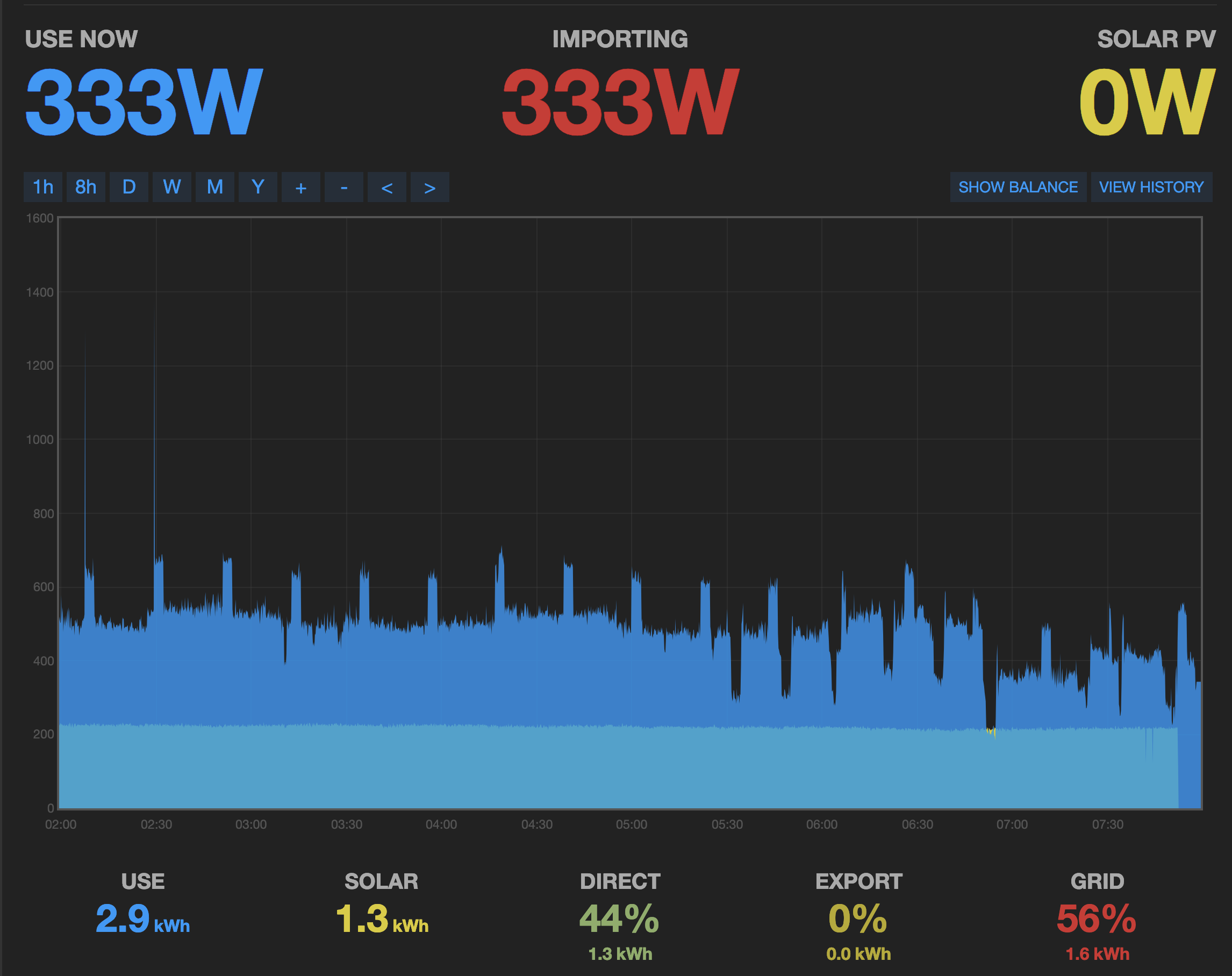
As you can see here…
The clamps are set just before a large breaker for the inverter, where it “merges” with the mains.
Tonight I might try to trip the breaker, just to see if it also turns off the inverter itself, because I guess this could be the reason… yet I feel that 200 Watts is not that great a “standby” for an inverter, but what do I know? . But even if it were the cause, shouldn’t it read a negative value then?
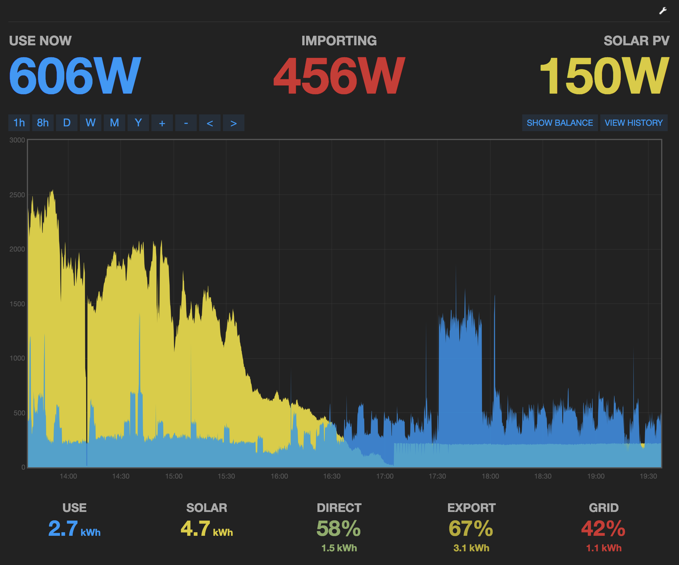
If it was noise and pick-up, I think the generation would merge into the steady line at 150 W. But because it suddenly pops up as the generation hits zero (or a small value), I think we can rule out those, and say it is something the inverter is doing.
Are you sure that 150 W is genuine watts?, i.e., have you got the power factor absolutely correct?
The explanation might be that it is the inverter switching into ‘sleep’ mode, and it is in fact a large current that is almost exactly 90° out of phase with the voltage, so in reality consuming very little power. But at that phase angle, a small uncorrected phase error between voltage and current will give both a relatively large power and a power that could easily appear in the wrong quadrant, so as generation rather than consumption by the inverter.
Hi again, and thanks for your input Robert.
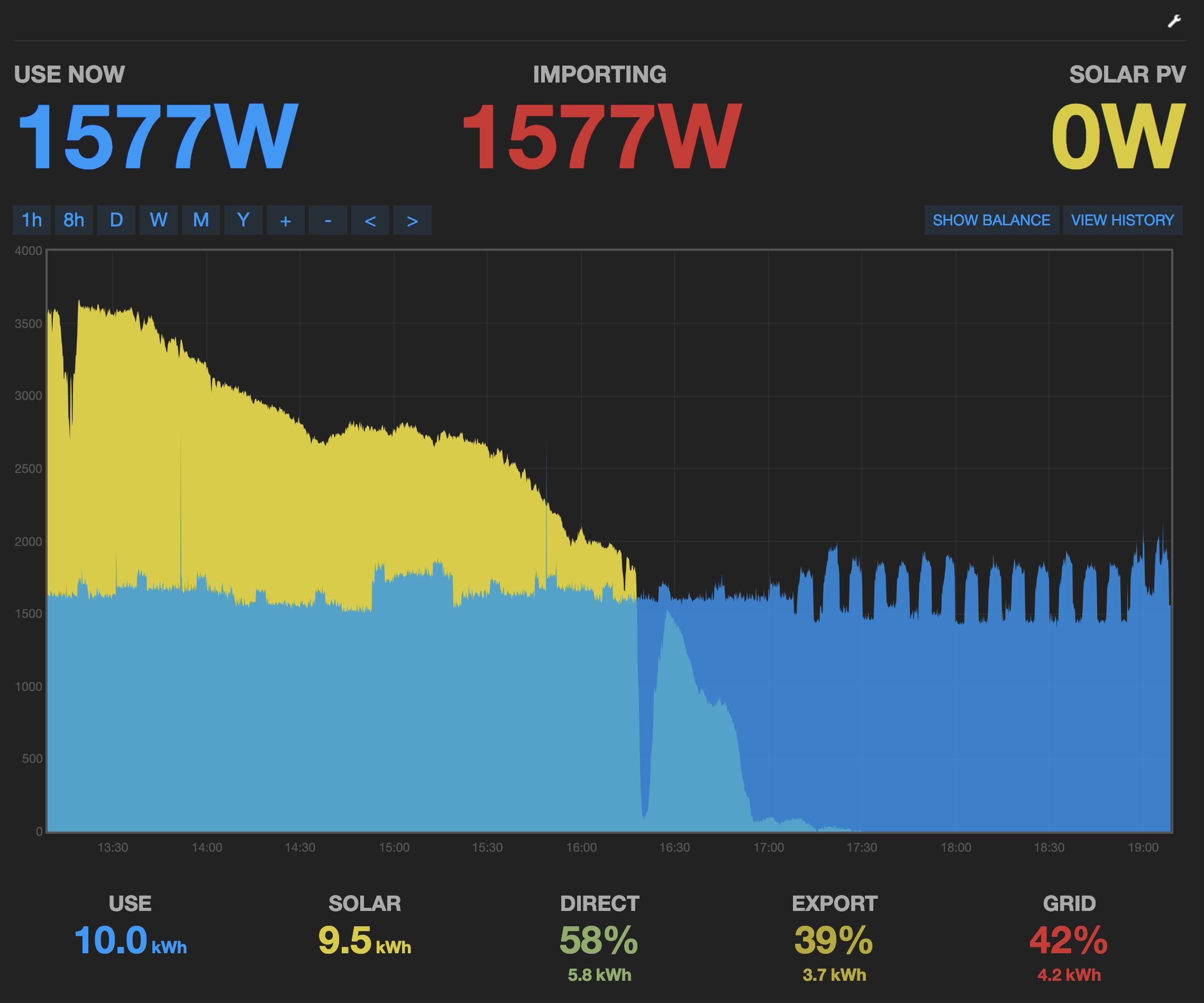
I have tried to switch off the breaker to the inverter input, and the inverter keeps running, so I guess it cannot be the inverter that uses the 200W at idle.
When the breaker is switched off, the values do zero out as expected.
I’m not at all sure that the watts are genuine or not, all I can say is that the clamps is picking it up . (the 200W is mainly on two of the three phases, and it is combined)
I do have three AC “power supplies” that I bought with the system, in order to pick up the voltage of each phase, so to make it more accurate, and I use the main unit (emon) for one phase, and have two external units for the two other phases (emontx).
Just for reference I have added a picture where the inverter input breaker is switched off. (it’s one breaker for all 3 phases)
I’m not sure what to do if my issue is indeed that the inverter is out of phase?
I think (but is not at all sure) that the inverter “adapts” to the mains frequency. I guess it must do, or else I would have some other major issues
But it was not always like this… at the start it didn’t have this issue.
Again a picture as documentation…
The first part of the graph shows when it seemed to work ok… then I think something went wrong (maybe only one phase it active)… I did have my electrician come bye and do some plugs from each phase so that I could have the AC PSU’s setup correctly…
And I am thinking, that maybe the order is not correct (I will have to double check), but could this be caused by an emontx attached to one phase with a clamp, and getting the AC from another phase?
“emon” is just our short name for energy monitor. What do you mean by “I use the main unit (emon) for one phase” Is that an emonPi? So how exactly are you measuring now?
Between 2:00 and 7:50, the 200 W is almost constant but it does get slightly smaller, then at 7:50 it fell to zero. What happened at about time 7:50? Is that
But at the beginning, you wrote
I think you had the wrong breaker. My understanding is, the inverter must always shut down when it is disconnected from the mains supply, because you must never feed back into the supply when it has been isolated for safety so that men can work on it.
This could be the big clue. I think you must check exactly which cables and which sockets belong to which phase and which rooms and appliances. If you then compare what you now have with that, it might explain what is happening.
I’m sorry if my update seemed a bit confusing.
My system consists of one emonPi and two emonTx boxes.
So the emonPi monitors two of the phases (one from the mains, and one from the inverter) and so does each of the emonTx boxes.
They are powered from the same phase via an 9V AC PSU.
And it seems that it is important that each unit monitors the same phase, which I think was my problem.
I had the electrician wire everything up some time ago, and I think I made it clear to him that it was important… yet as I have now found out there were several faults where the phases got mixed up.
I have managed to fix all that now, and it looks like it has solved my issue.
But of cause all my historical data is out the window, but I guess that’s my own fault for not having time to take a closer look at the problem for about 6 month
So the lesson for people with more than one pase like most of europe I guess: Keep the phases together one the same monitoring box.
Like: emonPi is powered via the 9V AC PSU from phase 1, and we measure the mains phase 1 as well as the inverters phase 1. And same thing for the two emonTx boxes.
I guess you can get away with only two “boxes”, but the accuracy will suffer.
Thanks again for great input, I’m now a happy camper
And oh yeah we are having some nice sunny days here in otherwise cloudy Denmark
Yes, although the emonTx with the 3-phase sketch can monitor a 3-phase supply, the measurement will be good estimate only because the second and third phase voltages are assumed to be the same as the first. The emonPi cannot use a 3-phase (or even a 2-phase!) sketch.
As you say, the most accurate measurement (with what we have) is to use a separate “box” for each phase, because that allows each voltage to be accurately measured. And each must only measure the currents on the same phase as the voltage.

 . But even if it were the cause, shouldn’t it read a negative value then?