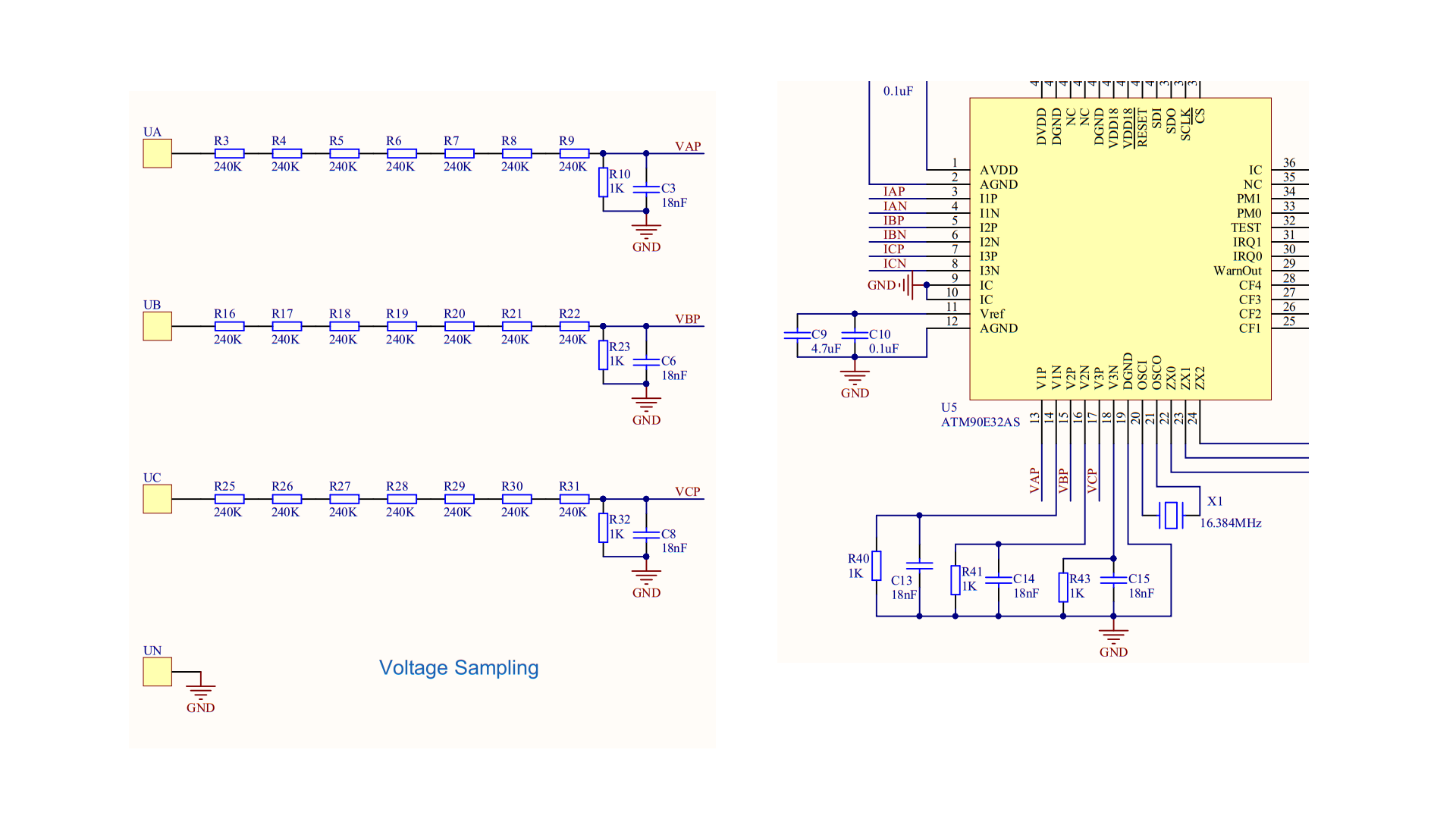
I’m a bit puzzled about the voltage divider configuration. The circuit model for the voltage divider is illustrated below:
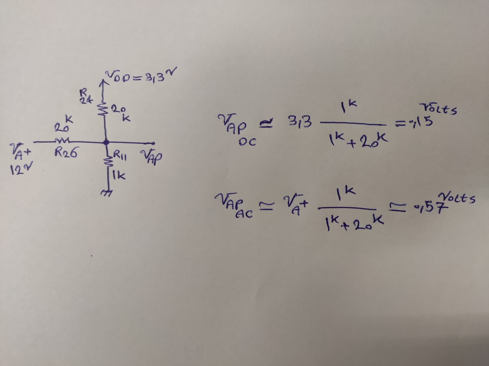
According to the schematic file, both AC and DC voltages are divided by a factor of 21, and the resulting output is then applied to the Voltage pin of the ATM90. I understand that, in some cases, a DC voltage equal to the half-wave magnitude of the AC signal is added to make it readable by the ADC port. However, it seems like the operating principle in this circuit might be slightly different.
Could you shed some light on the rationale behind the specific values chosen for resistors R26, R11, and R24? I’m particularly curious about how this configuration handles the combination of AC and DC signals.
Besides, As can be seen in the application note document of ATM90E32, VP pins are attached to a voltage divider and the VN pins are attached to ground trough a resistor.