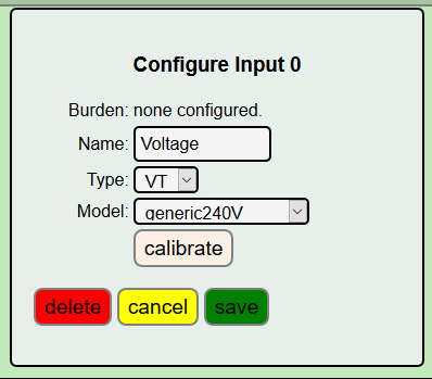
@Brendon: I made my own pcb from overeasy his schematic, adapting it to accomodate 3 dedicated VT channels. However, his solution to use 2 resistors (1 inline and one burdon) to change a CT input to a VT input is very esay.
I am planning to create a PCB once I have everything ironed out as well. I have the schematic drawn up and got a lot of it working already on a breadboard.
For me monitoring LED impulses from a smart meter is quite important. I wanted to be able to have the device auto-detect if i have one of these plugged in instead of a CT and I think I have a decent solution for this now (though not written the software yet). The 3 phase is not so important to me as I don’t have 3 phase in the new house, but is something I wanted to think about. Seems quite easy to permanently assign more inputs to VT’s, I was thinking there might be a way of auto-detecting like I plan to do for the LED but not really considered it yet.
@overeasy Congratulations on the release of IoTaWatt! It is a great achievement. I very much appreciate all you have done on this.
I have a near stock IoTaWatt built on a breadboard and all is working well. I wanted to start with stock and then add other things I care about after it is working.
Right now I am implementing another output service that can POST stats to pvoutput.org as this is primarily what I want to use it for.
Do you have any documentation or examples using the scripting language or web page config you implemented in the other output services loaded from config file?
I have a basic idea of the config from reading the code, but things will go a bit faster with some example configs.
Also, I need to calibrate my CT’s and VT. I am using SCT013-015 with no burden resistor as it has one built-in and a VT from a 9V AC plug-pack I just had in my garage. I measured the VT using a multimeter and it seems to be putting out about 11V RMS instead of 9V, after adjusting the calibration in the config based on this reading I seem to be getting good values for voltage now. Next week I am planning to use the oscilliscope at work to do a more accurate calibration.
Do you have information on best practices for calibrating these anywhere?
I have been thinking of creating a “calibration helper” web page where I can connect a known resistive load to a channel and it gives estimated values for the calibration constants.
Just answering part of my own question. I just saw the wiki, cant believe I didnt notice it before:
Right. Was just about to direct you there.
To use those VTs and CTs you don’t need to reprogram, or even restart the device for that matter. Configure the VT as a generic240 (assuming you are 240) and use the calibrate feature to fine tune the calibration:

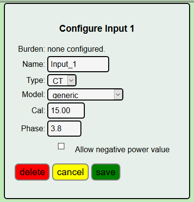
The SCT013-015 is just another variant of the SCT013-000 with an internal burden resistor. Assuming you have no burden on the designated input channel, specify burden zero for that channel in ![]() .
.

Alternatively, you could edit the Json TABLES.TXT file to add that voltage typr CT. Then it would be a menu pick in the configuration utility. Use the file editor app. Load the tables.txt file. I’d use the SCT013-030 as a model:
{"model":"SCT013-030","mfg":"YHDC","type":"V","cal":30,"phase":3.8},
Copy it to a new line and change it to this:
{“model”:“SCT013-015”,“mfg”:“YHDC”,“type”:“V”,“cal”:15,“phase”:3.8},
Note: anytime you edit these Json files, it’s best to copy and paste the edited contents into a Json checker like jsonlint to be sure you didn’t mess up the syntax.
In general, I recommend against using those voltage type CTs. The unburdened SCT013-000 will work just as well. For whatever increased resolution might be gained from using a high burden, the impact is a wider range on phase shift, especially at the low end where you are trying to gain accuracy. If you want to measure in a low current range, a better solution is to use a CT with a lower current ratio. The newly introduced (into the OEM shop) SCT006-000 has 800 turns and is rated to 20amps. They are inexpensive and tiny to better fit inside a panel.
Personally, and especially for hackers, I like the HWCT-004 solid core. They cost about $2. You have to add your own cord and jack, and because it’s solid core, you have to thread it onto the conductor rather than snap it on. But they are inexpensive, accurate, and have low phase shift. They can handle up to 40 amps with a current ratio of 1000:1, so twice the resolution of theSCT013-000.
There are quite a few comments in the code, available on Github. The scripting facility is handled by the Script and friend class ScriptSet. These classes build the internal tables from the Json objects in the config file, and there is a method to evaluate a particular script using callbacks to provide the real-time input values referenced in the Script.
I looked at the pvoutput.org site, and that would be fairly trivial to add as it’s really just a URL format difference from Emoncms.org or influxDB. I’ll probably add that, but there are other changes to server support that should happen first to create a different framework that supports multiple server instances. Probably a few months off.
Can we hack the IotaWatt as easily as the rest of the Open Energy Monitor hardware?
What I mean by this is that all the previous hardware allowed you to easily interface with other systems to create a better overall system.
Can we tap into the data from the IotaWatt and if so what is the procedure? I don’t want to see the data, on a website etc, I want to be able to touch it via TTL or similar.
The IotaWatt FW is full opensource and is easy to modify and compile (PlatformIO recommended)
By default the IotaWatt monitoring data is not printed to serial, the serial port is used for debugging. However, since the ESP8266 has got two serial ports the 2nd serial port could be setup to output monitoring data. Currently the easiest way to intercept the IotaWatt data is vi posting an an Emoncms sever (this could be local e.g. emnonPi / docker / ubuntu). MQTT support is planned in the future. @overeasy will be able to advise further.
Thanks @glyn.hudson but no thanks. Tried it and quickly went back to the trusty Arduino IDE.
I guess that’s the way we will go.
We don’t want the overhead of an additional server even at $10 for a Pi Zero W.
p.s. the hardware you sent me arrived safely today, very impressed thanks. Separate post to follow.
Haven’t had any use for that, but quick look it uses GPIO pins that are in use, in fact, all of the GPIO pins are in use.
There is an API to get data. You can get request any combination of raw input data and scripted output data, for any time period, either in volts, watts or watt-hours. Beyond that, you are free to embellish or add to the API capability by coding your own handlers in the web server portion of the firmware. You cannot touch it though, data is intangible.
Do you have a link?
@GeorgeB: if you look at the code of the “webserver” you can see the different keywords it uses:
ex: inputs are displayed with ip_of_iota/status?inputs=yes
outputs, frequencies, uptime,raw data, it can all be displayed 
I am also experimenting with this (due to bad wifi reception at the electricity case). I just use the main serial (the mini usb cable) to output the data. Ok, there are some status messages passing by, but EmonPi just ignores these. However it’s only running 34h like this, so no longtime experience yet.
Thanks @glyn.hudson I’ll take a look.
I see it’s just the regular emonCMS API. I could work with that but it’s far from ideal.
I’m taking a wild guess here but I suspect many users will not be hooking up the full 14 channels.
Is there any way of freeing up a GPIO so I can “touch” the data?
I’m a little confused.
@overeasy maybe look at the context.
Skipping about from thread to thread…
In any event, the API is not documented yet. It is a modification of the GET/FEED/DATA that Emoncms uses to feed the various reporting apps. The protocol is basically the same but modified to work more efficiently with the data organization on the Iota’s log file.
Probably the most complex part is determining the "feed-id"s to use in the request. That’s one of the things that is different from Emoncms. I have it on the short list to see if graph can use, or be adapted to use, the actual names assigned in the Iota config file with some pre/post notation to designate power or energy. Without getting into the exact syntax of the request, you specify:
The begin time in unixtime
The end time in unixtime
The interval desired in seconds
The feed id desired (or a json array of feed id’s)
The response is a json array (the time index) of json arrays (the feed id’s).
So if you requested:
http://iotahome.local/feed/data?start=1507840330&end=1507840340&interval=5&id=[01,12,13]
You might get:
[[120.0,204.7,3561.85],[119.9,161.7,3561.85],[120.0,175.2,3561.85]]
which is an array of three arrays at times (1507840330, …35, …40)
Each containing the voltage on channel 0, the power on channel 1, and the cummulative KWh on channel 1.
That was an actual transaction on my home IotaWatt.
The handler uses HTTP “chunking” so you can rip a lot of data without worries about buffering, but it is a little slow due to the SPI SD.
Looks to be suitable @overeasy do you have an ETA for the API?
Any thoughts on freeing up a GPIO or is that a none starter?
The API is there now. Id like to try to change the feedID part in the near future but might not be able to get to that. There is another API that also returns json and can be used to match input names to id’s:
http://iotahome.local/feed/list
If you have an iotawatt, try it, then try the feed/data/.
Don’t see it in this device’s future. The relief comes with a port to the ESP32, which I envision fitting in the same enclosure. Opens up a lot of opportunities. Timeframe? no idea.