Can you post the samples so I can see them?
I copy/pasted about 10 samples as fast as i could to a txt file.iotawatt samples volt.txt (84.4 KB)
They are all from channel 0.
In the mean time i also tried 2 other nodemcu but with the same result (even the one from the other IotaWatt that is working perfectly).
Just one thing i find strange: on the second board i used a shunt that according to my supplier (conrad - link - datasheet) should be 2.5V. However measuring it gives 2.0V.
I configured the IotaWatt with a reference of 2.0V and the measurements (lightbulb) are relatively OK (±3W difference on 100W lightbulb)
update: the value after the , seems to be the I value. Removing it from excel data it seems to shows a nice sine wave every time
I’ve taken a quick look at the samples. I wasn’t explicit, but when dealing with things like this I try to remove as many variables as possible to narrow down the cause. In this case, I am relying on your assertion that the problem exists with just one VT connected to the IotaWatt. That means noi CTs as well. Looking at the samples, it appears that there probably was at least one CT connected, and that it appears to be on a different phase from channel 0.
In some of the sample sets, I see a bias that is not at midpoint. That should not be the case. It may not be the source of the problem, but it is unexplained. Again, I don’t know what else is going on. It’s possible there is something going on with the three phase, so again, the problem needs to be recreated in its most basic form, one VT only on channel 0 - no CTs, and another set of 5 or 6 samples.
If the bias still looks to be wandering, I would start to look at the reference going into the ADC and the OPamp (I think in the version you built, there is an unused channel on that dual LM358). Another thing I would try is using a channel on the other ADC to sense voltage. Leave the 24 ohm burden and connect a VT with about a 300 ohm 1/2 watt resistor in series. Don’t bother calibrating, just see if it behaves with a steady voltage.
Even a cheap USB oscilloscope like the low end Sainsmart ($50) would allow you to monitor the bias voltage and go a long way toward debugging this board.
The samples i provide were taken with 2 VT and 10CT connected, some on vt1 some on vt2. (i didn’t know it would matter) If you want, i can take some measurements on sunday (i’m away from home now) with only one VT connected.
I’ll also look into your other suggestions and connect a vt with the resistors to a normal channel!
I don’t know if it matters either, that’s why I want to eliminate it as a variable. By narrowing the scope of possibilities, the problem is greatly simplified and clarified.
Yes.
Also, is the other device currently working polyphase?
I took some measurements with only one VT (channel 0) connected: iotawatt samples volt2.txt (65.4 KB)
Plotting them in excel shows a sine wave, but it seems to be incomplete (it doesn’t end at 0)
I also connected the VT to channel 14 (so on the MCP3208) but it acts the same.
The other Iota is currently connected to 2 VT (the 3th vt is still connected to my old system) and runs good 
@promy can you provide an image of the clipped sine wave?
@GeorgeB: attached is the graph made in excel
I remembered that i once made a (el cheapo) soundcard osciloscope and hooked it up to the AC adapter. i could see the spikes. Connecting it to the BIAS and to the 2.5V (actually 2.0V with me) and i didn’t see any movement.(for what’s that reading is worth off course…
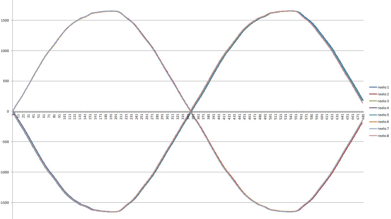
These all look fine to me. They are all complete. The sample set begins with the first sample after zero cross and ends with the first sample after the third zero cross. Zero cross is the point of maximum change, and if you look at the samples at the midpoint zero cross, you’ll see that it’s typically about 15 counts across zero there, whereas at the peaks - point of minimum change - there is virtually no change for a couple of samples. That’s normal.
Of the 12 sample sets you published, none are extraordinary:

The variance in RMS is hundredths of a percent. So the question is are you seeing the voltage fluctuation when configured this way? and where exactly are you seeing the fluctuation - is it the CAL routine, or the status display?
Yes, i am seeing the fluctiations when configured like this (i checked before taking the samples.)
They are most obvious in the CAL routine, but also visible in the status display (but much slower)
To illustrate the “problem” i made a smal video on youtube: https://youtu.be/cdfYyMzrOlE
and a second one on the inputs pagehttps://youtu.be/qFqtiLQYkzc
I can hear you screaming at the start of the CAL video. Pretty good problem, but not that bad.
When I look at the status screen video, I am not convinced of a problem there. It does take a dip in one refresh, but for the most part stays within 1%. I don’t know how volatile your voltage is, so you be the judge.
The CAL screen is definitely animated. There are two areas that I would investigate:
First, I have to wonder if there is a problem with you voltage supply (You probably swapped with the stable unit to rule that out, but nevertheless…).
I wonder if there is a problem with the voltage reference shunt. If you are getting consistent rms sample sets, then the conversion of those numbers to actual volts is a function of the reference voltage. Could that be defective or cold-soldered? The 1K resistor as well and the trace to the ADC. If I were looking into this area, I would add another column to the sample array and add a readADC of the shunt channel to each sample pair. That should be within one count in every sample, and across all sample sets. Any variance in supply voltage will show up there. It’s about 780uv per count, so with a 2V shunt you should be seeing a value in the 2560 neighborhood. Once again, an oscilloscope would be handy here.
Let’s see if any of this yields enlightenment.
That was my son over here ![]()
The strange thing is that the other Iota does not have this behavior with the same VT (and the other 2 VT’s i have show the same result: stable on the 1st Iota, non stable on the second). It stays within 0.3 to 0.5V.
The only difference between the 2 iota’s is the voltage reference shunt. The other one has a 1V version and this one a 2.5V version (but it only gives 2.02V…). So i’m guessing that it may be the problem. I’ll reheat it again or maybe replace it.
According to the soundcard osciloscope the voltage seems to be stable.
Just to rule this out, i ordered a new (1V) shunt.
I’ll try to add the other column to the sample array, but i’ll have to think how to do this ![]()
Update: am i correct that the function getAref gets the info about the adcreference?
Not sure I can say that. getAref() does read the reference voltage channel and subsequently computes the apparent reference voltage of the ADC. My suggestion was to monitor the ADC reading directly but either way should demonstrate the stability of the supply and voltage reference. readADC() yields an inteer betwen 0-4095. getAref() will return the float voltage value of the supply as indicated by the assumed constant reference. The integer can be saved in a uint16_t variable. The float requires twice the storage in the array.
I changed the voltage reference with a 1V version, and now it runs just like the other one: minor changes. so it must have been a foulty shunt.
That was on the short list.
@overeasy presumably the IotaWatt 4.X could have been designed to use the AC - AC adaptor to power the device? What I mean by this is that technically it would be possible.
Fair enough. The schematic is on github. Propose something.
@overeasy First off, thanks Bob for Iotawatt. It sounds like you’ve put a ton of time and resources into it’s development. I have a breadboarded version in my garage and working well so far paired with some 3110-3000s.
I’m planning on doing PCB layout reusing the parts that I have (adafruit SDcard, shut voltage reference, RTC, and misc DIP ICs) but haven’t found an enclosure that I’m happy with.
Are you able to reveal your supplier for the commercial Iotawatt enclosure? It looks like a really good match.
1 Like
Takachi PF13-3-9
I am working on a change to hardware and software to support powering the device + measuring from the same AC plug pack. Once I have something working I plan to put my work up in github in case it is useful to others.
From reading the forums Bob has been focused on getting IoTaWatt ready for manufacture and I think has done a great job preventing feature creep that would have delayed things.
I have a design that I think should work and am in the process of prototyping it on a breadboard. The current draw on the AC plugpack will introduce inaccuracies in the voltage measurements as previously mentioned. I have yet to quantify what that introduced error will be.
The key things I want to do differently with my homebrew IoTaWatt are:
- Support LED monitoring for data logging from smart meter (1wh light pulses)
- Support pvoutput POST (Using a generic POST format string so can configure for multiple different types of services instead of new “service” implementation for each type)
- Power device from single 9V AC voltage input in addition to sampling it for power calculations
- Support 3x AC plug-packs to handle 3-phase power
- Support auto-detect input channel type of the ADC (AC vref, CT, LED monitor or unplugged)
- Try a few ideas to improve accuracy
I probably wont get around to all those things.
1 Like