Holes in the data from EmonTX to EmonBase/RFM69Pi?

I’m not sure if this is hardware issue or a software issue, so mods please move this thread as needed.

I’ve just switched over to from using a DIY USB Arduino/RFM12B box connected to my home server to using a EmonBase (RPi2+RFM69Pi on 868Mhz) on the latest EmonSD image from the 3rd May.

It’s been running a few hours and picking lots of data and posting it to emoncms,org, but I’m seeing lots of gaps in the data from missed packets, every few minutes. It’s making the graphs look rather untidy :frowning: and presumably messing up the totals too. My DIY box only missed them very infrequently, it could go days without missing a single packet from the EmonTX. Both the DIY box and the Pi are in a cupboard about 4 feet and internal walls from EmonTX.

Is this normal behaviour for the RFM69Pi?
I’ve turn on the “quiet=false” in EmonHub and there are lot of discarded frames, but it seems to be raw bytes, so a bit opaque. Any ideas or suggestions? :slight_smile:

Lee,

In order to help you, Paul will need to look at your emonhub log. Can you post a copy of it?
If your log is large, it’s OK to post it as a zip file.

No problem, it’s been a while since I used SCP… :persevere:

Looking through it now, there are quite a few banged up Node10 packets from EmonTX, but oddly, some that seem OK.
Look at 2016-06-13 21:30:35, it seems fine to me, node 10, some power, a bit of solar, no EV charging and some voltage, but still gets discarded. Odd.

emonhub.log.zip (96.3 KB)

Which model emonTx? the packet looks v2ish. Is it a stock firmware? How is the emonTx powered? Does it have deep sleep routines?

The packet you point out is just one occurrence so we can’t get a full picture from that alone but the “128” in that packet sticks out like a sore thumb and is possibly a single bit out of place causing the crc checks to fail. It looks vaguely similar to an issue found on the emonTh’s when the rfm69 was being woken up. (see the emonTH Unreliable reading timing thread for more info on that) but that’s not something we’ve seen on an emonTx (yet?).

Hi @pb66 I’m pretty sure it’s a V2, with an RFM12B. Bought as kit maybe three years ago.

It’s got basically the stock EMonTX_CT123_Voltage firmware, with just the calibration changed and one line added -
if (emontx.power2 < 15) { emontx.power2 = 0; } // measuring error during the night
to remove some rare glitches I was getting from the PV during the night.

It’s got a decent (Samsung I think) USB phone charger as a PSU and AC adapter bought from the OEM shop.
It’s the stock firmware, so has the emontx_sleep routine, though oddly, I’ve not noticed it before, it does a emontx_sleep(5).

I’m not sure the problem is the EmonTX, I think it may be the RFM69Pi. It’s the only RFM69 in my whole setup reading a pile of RFM12B’s. My other receiver was a arduino/emontx shield (with RFM12B) with USB as a gateway to my server, like I mentioned above it rarely misses a beat. Hence the finger of doubt pointing at the RFM69Pi.

Just looked at the thread you mentioned, I’ll read it fully in the morning - it looks like it needs someone who is fully awake! :slight_smile:

Urgh! Seems to bet getting worse…

@Vester,

Are the remote nodes predominately using RF12B modules with the large, metal can crystal?

@emjay that sounds like a leading question! Yes, they are all RFM12B’s and I’m pretty sure they all have the large oval-ish metal can crystal. Why?

Hi Lee.
can you provide some more logs from emonhub of when the fault occurs, we can’t really pick out a pattern or base a diagnosis on the one occurrence.

It could simply be that the rfm69’s stronger receiver is pulling in more interference/noise which it is discarding but in the time it takes to receive and determine a packet is garbage, it may have missed a good one.

You could try updating the rfm2pi’s firmware as JeeLib has been updated and I believe the rssi threshold has been revised so a significant chunk of those weak packets could be discarded sooner in the process and hopefully catch more good ones. You should recompile your own copy or use this test firmware (taken from the RFM69Pi stops updating/freezes thread started on the old forum)

The issue with the example packet is a different thing as it failed crc and has a good rssi, so it maybe that you have more than one issue, perhaps this pre-dates the swap to rfm69, but you were unaware as enough packets were getting through.

@Vster,

Just about enough data in that log to do some analysis. There are several issues here. Looking at the error rate per NodeID, you will see that it does not correlate to signal strength. This potentially rules out environment factors like background noise level.

There is some other common factor causing the excessive packet loss and different nodes have widely different loss rates. The common factor here is a single RFM69CW (SMD crystal) listening to multiple RFM12B’s (metal can crystal). The metal can crystal is ~ 15-20ppm but tends to be trimmed on the low side of the target value. The SMD crystal is ~10-15ppm but tends to be trimmed on the high side of the target value. What is probably happening here is that you have an outlier ‘high’ crystal on the RFM69CW. Each node has it’s own definition of 434/868 Mhz, derived entirely from the local crystal. Small variations are inevitable and normally the AFC on the receiver adjusts to this ‘on the fly’ per incoming packet.
Here the deltas are right on the limit of what the AFC can cope with (NodeID 21 is the most extreme). This results in a seemingly strong Rx signal not fitting properly into the Rx bandwidth, this then biases the FSK decode to one side (in this case inventing 1 bits where there are really zeros)

The simplest fix is to make a single change on the RFM69 driver side. Instead of setting up as 434.00/868.00 MHz in the rf69_initialize() call, set slightly lower. Try 433.995, 433.990 … (867.99, 867.98 …) This is easily done with the fourth parameter of rf69_initialize() which is a fine adjustment offset, defaulted to 1600. Reduce by 1,2 … to get the new frequencies shown.
The effect will be almost nothing, then dramatic improvement for the least delta nodes, then all, then finally errors coming back in if you go too far with the adjustment. From the data, I’m estimating 3 - 4 ticks is probably the sweet spot.

With this out of the way, there are at least two other lower priority issues (incorrect noise floor setting, packet bit slip, bizarre RSSI for NodeID 10?) - it will be easier to deal with them looking at a fresh log after the tuning.

If you are wondering why the symptoms looked even worse in your last report, the raspi may well have been running at a different temperature - this is so close to the ragged edge, the small change of crystal frequency with temperature pushed the deltas even further apart.

(edited for multiband)

I have similar and have always assumed this is the way it’s supposed to work. My emonTX is 20cm from my emonpi. So, I’ll re-read the above, but to be clear, what am I looking for in the logs?

@peter,

Maybe, but there are several other possibilities for poor reception, especially the Raspi world which can be quite noisy at RF, depending on specific grounding, PSU used etc.
You could post a similar log for a quick look - one aspect that helped this analysis was to have multiple sensor nodes chatting to central. Your configuration is similar?
BTW, 20cm is much too close - the Rx signal is strong enough to overload the RFM69 front end, leading to decode errors.

1 Like

Ok, so I thought I’d start with the easy stuff first. I downloaded the test hex file that @pb66 suggested and managed to Avrdude it into the RFM69Pi. It failed with an error near the end -

avrdude-original: verifying …
avrdude-original: 8818 bytes of flash verified
avrdude-original: safemode: lfuse reads as 0
avrdude-original: safemode: hfuse reads as 0
avrdude-original: stk500_cmd(): programmer is out of sync
strace: |autoreset: Broken pipe

But I’d guess the programming worked. It started running at approx 9pm and it’s hasn’t missed a beat since.
Interestingly all the diagnostic messages have gone too. Is this is correct?

I’m now working on compiling my own hex with the param change as suggested by @emjay
Back soon…

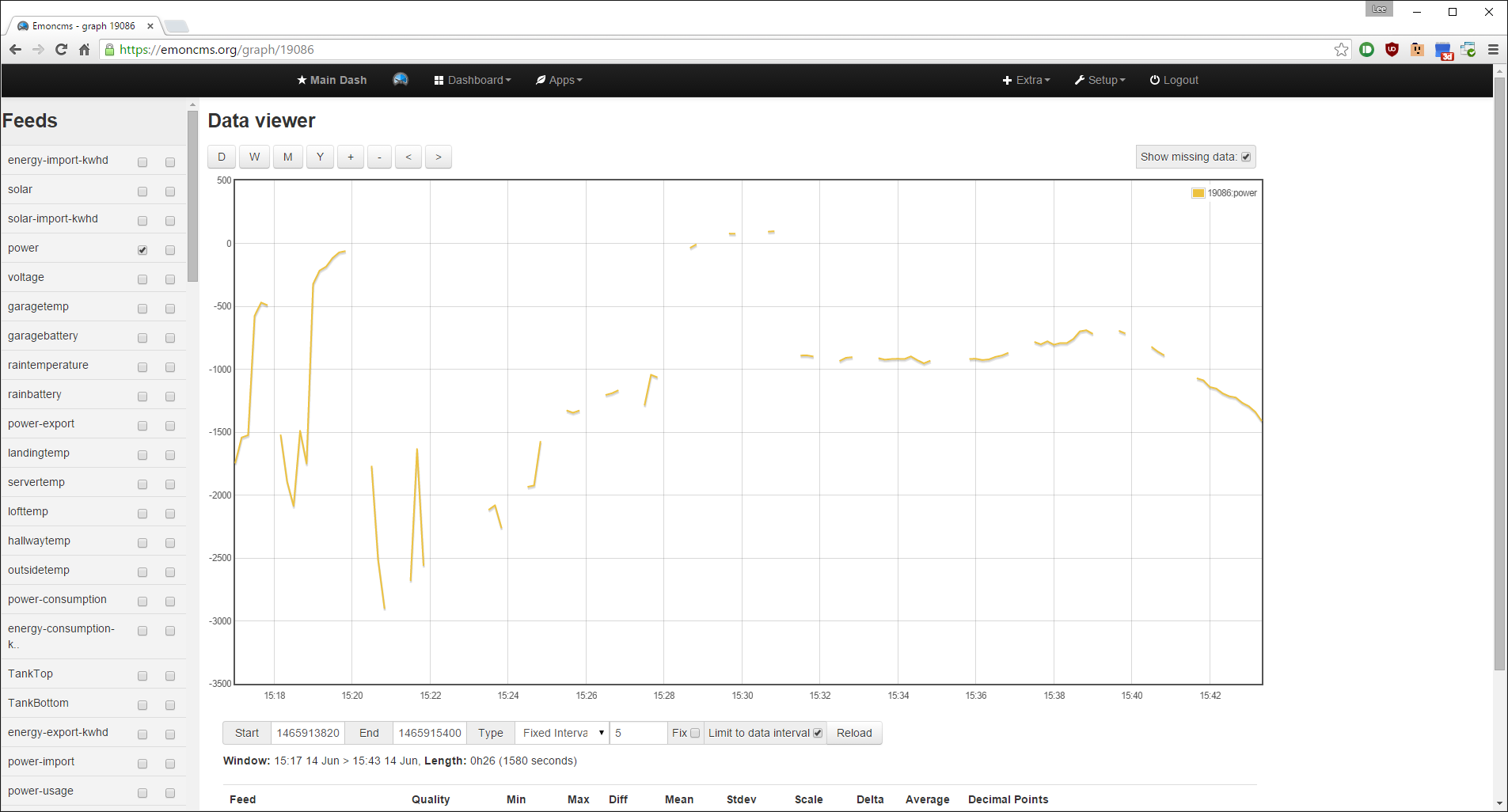
@peter - The graphs in emoncms can be misleading as results will always look much worse when using a fixed interval feed to record non-fixed interval data,

Depending on the sketch used the send interval may not match the fixed “save” interval, even if set to a fixed period in the sketch, the use of sleepy_lose_some_time could have a huge impact on the accuracy of that.

Then there is the “wait til it’s clear to send” function of the rfm devices and also the time taken to arrive at emonhub where it gets a timestamp.

See RF69 reliability, timing, temp sensors, mqtt & lowpowerlabs for a discussion on this. I have installations where I have recorded delays of up to 6 secs in transmission times due to rf clashing, that 6s delay can result in one empty “fixed-interval” datapoint, and then get overwritten by the next transmission if it on time and before the next “fixed-interval” save time.

That thread lists 3 reasons a packet could fail to be received

  1. corrupted packets when the rfm is being woken from a deep sleep too close to sending data.
  2. “bitslip” from long runs of zero’s
  3. sketch send intervals being too long to match a fixed interval

3 is primarily about setting a 10s sleep so the interval becomes 10s plus loop run time and shortening the sleep can work but allowance for timekeeping discrepancies need to be made which result in packets being discarded (overwritten) by emoncms PHPfina, eg 9s to be safe will be updated twice and saved once within a 10s interval 10% of the time. There are the other timing issues too

  1. packets that are delayed momentarily due to a noisy network
  2. lose_some_time extending the send interval beyond the fixed interval if interrupts are used (pulse counting)

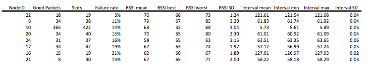
The bottom line is you cannot use fixed interval feeds to assess packet reliability, you need to use a phptimeseries to confirm what packets you receive when.

item 1) was identified and has been fixed in the emonTH sketches by adding a small delay, it hasn’t been reported in other firmware but it is possible it could crop up else where.
Item 2) has been tackled in OEM sketches by using a non-zero out of range value for unused temp sensors.
item 3) has been improved by reducing the sleep times to allow for looptime in the later sketches but older devices may still be using the older firmware intervals
item 4) maybe improved by using later rfm2pi (recompiled with later JeeLib) firmware as the rssi threshold is higher
item 5) should only be an issue if pulse counting, the only sure fire way around this is to not reset millis() in the sleep routine I guess

Overall there is an ongoing incompatibility between fixed interval feeds and non-fixed interval send intervals, it has been improved but it cannot be eradicated unless some sort of polling or a way of identifying and correcting a late packet is implemented.

@Vster - the test firmware has had the help text restrained to a “h” command to make the logs easier on the eye and reduce any chance of rogue commands being accidentally issued during the needless printing and exchange of serial prints.
You can confirm the firmware has uploaded using a “v” in a serial console, checking the emonhub.log for the startup period or by reseting the rfm2pi, the led will flash rapidly 5 times for easy identification. aside from that the sketch is pretty much unchanged, just recompiled with the latest Libs.

1 Like

Thanks folks. I’m well behind on emontx firmware, as established in earlier threads, and I will do something about it as soon as I find the damned USB dongle.

I’ll add a single phptimeseries log at the top of one of the inputs just to track the underlying data for a few days.

Hi @pb66 and @emjay!
Sorry for the extended disappearance, I’ve been testing a myriad of firmware on the RFM69Pi!

@pb66 I tried your test firmware, this helped a lot, it went down to around 1.5-2.0 misses per hour. Not bad out of 360 transmissions. The only thing is the “h” command from minicom still shows the full help text, the “v” command shows “[RFM2Pi v1.1 (rfm69)] O i15 g99 @ 868 MHz”. So is the the test firmware you’re thinking of? Also is the source code available somewhere?

Sadly I wiped the existing firmware before I thought to run a “v” on it. :frowning:
It’s odd that it was that bad, I wonder what it was?

@emjay I’ve recompiled the latest source from here on Github -

RFM2Pi/firmware/RFM69CW_RF_Demo_ATmega328/RFM69CW_RF12_Demo_ATmega328 at master · openenergymonitor/RFM2Pi · GitHub

using the latest Libs from JeeLabs and the frequency adjusted.
Even without adjusting the frequency, it was a lot better, similar to the test firmware from Paul.
It’s only this morning that I’ve realised I’ve changed the wrong value (I think) as there are two places where the 1600 frequency adjuster is mentioned. I’ve fixed that now and am letting it run for 24 hours.

This leads me to the next issue about the RSSI. Considering the EmonTX is only around a metre and two internal block walls away from the RPi, it seems that the signal strength is a bit low at -64ish. This is backed up by my lounge sensor being a further 3 metres and 1 more wall away being -65ish. The two in my kitchen (about the same distance as the lounge) get about -72. The one in my garage has dropped off the network now, it was getting into the -80’s, but the old RFM12B picked it up ok.

So, is there anything I can do about this hardware wise? Or is this this still firmware related maybe?

Good to hear you are making progress.

The replies to the “h” and “v” sound correct for the test firmware, so yes it looks like you have the correct hex file and it installed correctly.

I wouldn’t worry too much about not getting any details from the original FW, the truth is there has been very little change in the FW since it’s release but the changes that have been made have not resulted in a revised version id and the IDE and lib version were not recorded so there is no surefire way to tell the exact version.

The results from the test FW should indeed be similar to a recently recompiled hex of the original FW as there were no major changes made, it was more about ensuring the latest libs were used and that everyone involved with diagnosis of the issue in that thread was using the same FW.

For that reason I haven’t made the source available so any copies out there will have been compiled at the same time, using the same libs in the same ide, making diagnosis easier with a level playing field.

The rssi values are not unusual, I get what you are saying about the additional wall and the difference in distance, but it is not a straightforward science that adheres to simple rules, the signals bounce around and get influenced by other things such as interference etc, not to mention tolerances in components etc so while your observations are sound and make sense, they are also possibly not a cause for to much concern.

The garage node is a bit of a concern though and that will be due to the signal threshold being changed in JeeLib. I too had a garage node that was regularly in the -80’s but I added a ground wire to my JeeLink (usb rfm2pi) prior to the lib changes, so adding a ground wire the same length as the antenna wire (to either the rfm2pi or the emonTx) and extending it in the opposite direction to the antenna to make a dipole might be worth a try and may well improve things, I gained ~10db rather surprisingly and the successful packet reception increased dramatically, I was previously losing around half the frames due to the weak signal. .

Definitely worth the effort. A quarter wave monopole sans ground plane (or wire dipole element) is a poor performer compared to a half-wave dipole.

Right, as it happens the antenna on that node was already a half wave monopole. So I added a half wave ground wire and turned it into a dipole. On the bench in my study it went from -80 to -65 rssi. I took it downstairs (more walls) and it went to back to 80. Back out to the garage and the signal disappeared again.
So I guess the next thing is to add a half wave dipole to the RFM69Pi?

What you’ve got is a full-wave dipole. Impedance at the feedpoint is greater than 1000 Ohms.

Change each element to a quarter-wave. That will give you a half-wave dipole and drop the feedpoint impedance to ~73 Ohms, a much better match for the RF module, which has an impedance of 50 Ohms.
(Note that the module’s RF port impedance is bit settable to either 50 or 200 Ohms)

Mismatched antennas are a double-edged sword. They reduce the effective radiated power of the transmitted signal and they attenuate the received signal by the same amount.